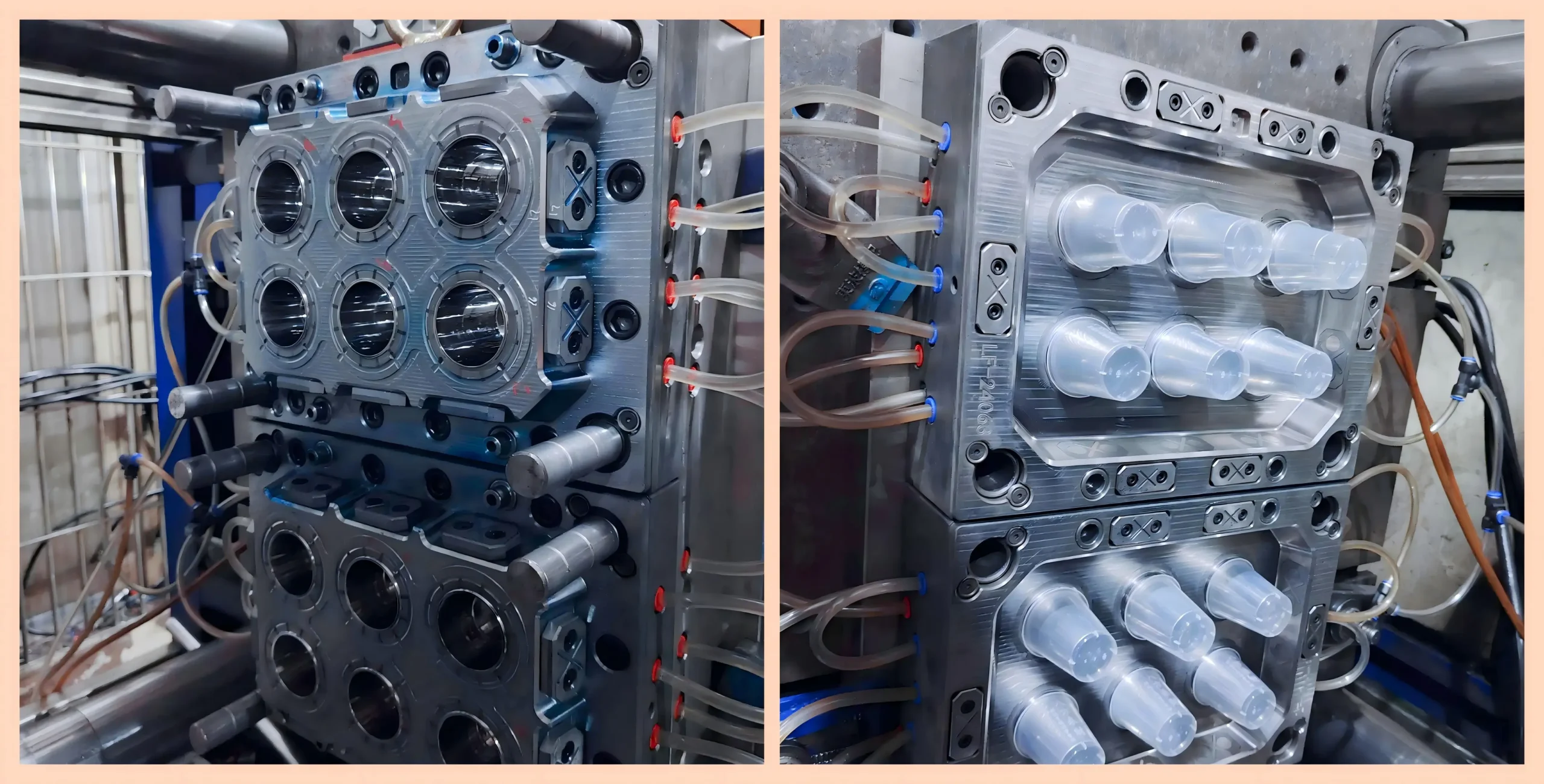
When you approach mold makers with a 0.8 mm enclosure drawing, almost every shop will say they can build it. However, some design the tool specifically for thin-wall molding, while others quote a conventional mold structure—only to run into short shots and burn marks during mold trials. To tell the two apart, draw a clear baseline: if wall thickness is under 1.0 mm (or up to 1.5 mm in broader definitions) or the flow-length-to-thickness ratio (L/t) exceeds 150:1, the tool requires a dedicated thin-wall Injection Mold design.
A thin-wall mold is not simply a conventional mold stripped of excess material. It is engineered from the ground up to withstand extreme injection speeds and pressures. Gates, venting, cooling, steel rigidity, and ejection—all five subsystems must adapt together. Once you understand the specific configurations across these five areas, you can instantly tell whether a supplier’s tooling proposal truly meets thin-wall standards or cuts corners.
What Defines Thin-Wall Molding?
Is 0.8 mm considered thin-wall? What about 1.2 mm? Measuring nominal wall thickness alone isn’t enough. In practice, the industry relies on two benchmarks.
The first benchmark is nominal wall thickness. The injection molding industry generally defines parts under 1.0 mm (and up to 1.5 mm under broader criteria) as thin-wall parts. Large components follow different rules—a 2.0 mm automotive interior panel can also qualify as thin-wall because “thin” is always relative to the overall part size and melt travel distance rather than an absolute number.
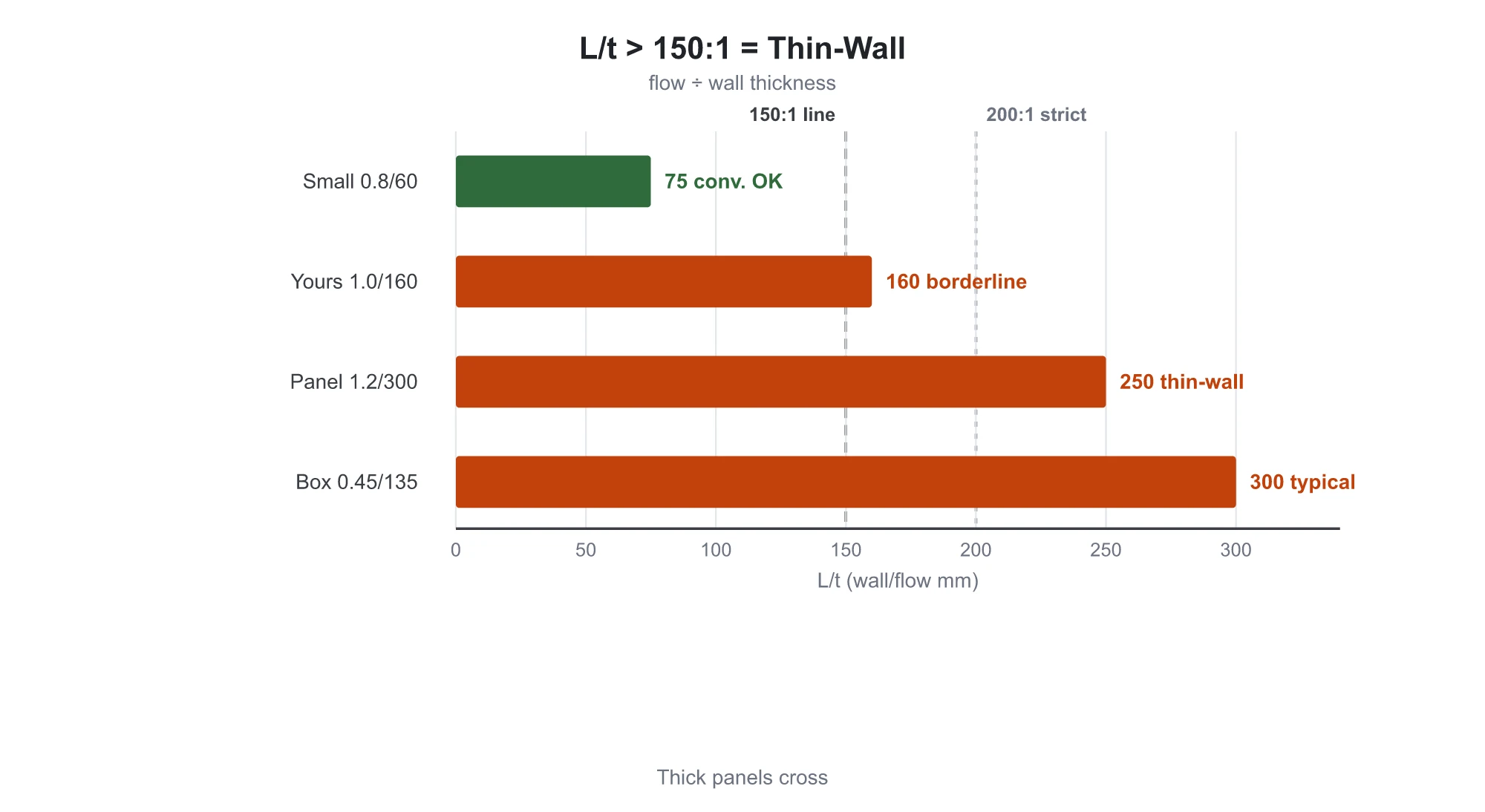
The second, more reliable metric is the flow-length-to-thickness (L/t) ratio—the longest melt flow distance divided by the nominal wall thickness. Flow length measures the distance from the gate to the furthest cavity point, which you can pull directly from the part model. When the L/t ratio exceeds 150:1 (or 200:1 in stricter shops), you must treat the job as thin-wall molding. You can run the numbers yourself: a disposable food container with a 135 mm flow length and 0.45 mm wall thickness yields an L/t ratio of 300 (135 ÷ 0.45). If your part has a 1.0 mm wall and the melt travels 160 mm, the L/t ratio is 160—crossing right into thin-wall territory.
Large flat panels cause the most common misjudgments: a 1.2 mm wall might look thick enough, but a 300 mm flow length yields an L/t ratio of 250:1, demanding full thin-wall processing. Conversely, a small 0.8 mm component with a flow length of only 60 mm gives an L/t ratio of 75, which conventional tooling can easily handle.
Resin selection matters just as much. A polypropylene (PP) grade with a Melt Flow Rate (MFR) of 12 g/10 min runs smoothly on a standard 2.0 mm part but causes 100% short shots on a 0.7 mm thin-wall part. Thin-wall molding demands high-flow resin grades: MFR 30+ for commodity plastics and MFR 15–20+ for engineering resins. Resin properties and mold construction go hand in hand—a detail frequently overlooked during project scoping.
Applying these two benchmarks gives you a clear answer on whether your product falls into conventional or thin-wall tooling.
Why Thin-Wall Mold Structures Must Change
Every injection mold executes five core process steps: plastic melts in the barrel, injects through the sprue, runners, and gates into the cavity (filling), packs under holding pressure to compensate for shrinkage, cools along water lines to solidify, and ejects via pins. Conventional and thin-wall molding follow the same process sequence—the divergence happens entirely during the injection-filling stage.
The divergence comes down to a single physical challenge: thin-wall molding races against freeze-off. In a 2.0 mm conventional part, the core remains molten even as the outer skin solidifies, allowing injection fill times of 1 to 5 seconds. In contrast, a 0.8 mm thin-wall part makes instant thermal contact across its cross-section. As the frozen layer grows, the flow channel narrows rapidly, forcing fill times down below 0.5 seconds—and as fast as 0.05 to 0.15 seconds for extreme 0.5 mm parts. Any delay freezes the melt front before it reaches the cavity end, causing immediate short shots.
Capturing this narrow time window requires aggressive machine parameters: injection speed jumps from 50–200 mm/s to 300–600 mm/s; injection pressure doubles from 70–140 MPa to 140–250 MPa; and required clamping tonnage climbs from 0.3–0.5 tons/cm² to 0.5–0.8 tons/cm² based on projected area to prevent flash along the parting line under high pressure.
While these speeds and pressures dictate machine specifications, the mold bears the actual physical burden. Doubled pressure loads the mold steel directly, while a melt front moving several times faster forces complete redesigns of gates and venting. The payoff is substantial: thin-wall cycle times run 2 to 5 seconds compared to 15 to 60 seconds for conventional parts—a 5x to 10x throughput gain that drives production economics alongside resin savings. Every structural difference across the five mold subsystems stems directly from these physical demands.

Gating and Runner Differences
The melt must enter the cavity efficiently, making the gating system the first critical barrier.
Standard mold practice is familiar: single-cavity small-to-medium parts rely on a single pinpoint gate or submarine (sub) gate. Gate diameters follow standard 0.5–1.5 mm rules, with runner balancing applied to multi-cavity layouts.
Thin-wall molds require three fundamental changes:
First, gate thickness cannot be significantly thinner than the nominal wall. Industry standard sets gate thickness at 70% to 100% of nominal wall thickness. If the gate freezes prematurely, holding pressure cannot pack the cavity, resulting in short shots and sink marks. Packing time in thin-wall molding lasts only 0.5 to 1.5 seconds (compared to 3–10 seconds conventionally); packing longer does nothing as walls freeze instantly, and excessive pressure only flashes the parting line.
Second, gate types must adapt. Wide, flat parts require fan gates to distribute melt evenly and prevent local hesitation or compression. Long, narrow geometries exceeding 100 mm in flow length require multi-point gating. For high-volume production, sequential valve-gated hot runners open gates in controlled stages, relaying the melt forward smoothly instead of surging all at once.
Third, runners must be short, thick, and balanced. Proven industry guidelines specify main sprues/runners at 8–12 mm and branch runners at 6–10 mm. Long, winding runners cause severe pressure drops. Because thin-wall molding trades injection pressure for fill speed, excess runner losses starve the cavity ends.
When reviewing tool quotes, a single sub-gate reflects conventional thinking, whereas fan gates, multi-point gates, or sequential valve gates confirm a true thin-wall approach.
Venting: The Biggest Point of Failure
As melt surges in, trapped air must escape instantly. Among the five subsystems, venting fails first on thin-wall molds.
Air inside the cavity cannot simply disappear; it must evacuate at the exact speed of the advancing melt. Trapped air compressed by high-speed melt heats up instantly to 400–500 °C, scorching dark brown burns onto the plastic—a defect known as “dieseling” or “air traps at the end of fill.” Minor traps cause localized short shots and discolored weld lines, while severe dieseling pits and erodes the mold cavity itself.
Why does conventional venting work for standard molds? Perimeter parting line vent slots sized by resin viscosity are usually sufficient: 0.01–0.02 mm deep for high-flow resins like PA and POM, 0.03 mm for ABS, and 0.02–0.04 mm for high-viscosity PC and PMMA. Deeper slots cause flash, while shallower ones choke airflow. Covering 10% to 15% of the parting line perimeter satisfies standard molding requirements.
Thin-wall molding fails because of extreme speed: melt fronts travel at hundreds of millimeters per second rather than dozens. Natural clearances around ejector pins and parting lines cannot evacuate air fast enough. The resulting backpressure creates an air cushion that blocks the melt from reaching the end of the cavity—meaning short shots and burns often share the same root cause. As a result, thin-wall mold venting requires a four-level architecture:
Level 1 uses parting line vent slots covering roughly 30% of the perimeter—two to three times conventional coverage. Level 2 adds vent inserts behind wide, thin surfaces, oriented perpendicular to weld lines for maximum efficiency. Level 3 places porous venting steel inserts (sintered steel) or vent pins at deep rib ends. Level 4 uses in-mold vacuum evacuation for critical medical or optical components, pulling negative pressure before injection. Vent slots must be machined by Wire Cutting / EDM to ±0.002 mm tolerances—a fraction of a hair too deep causes flash, while too shallow blocks air, exceeding standard CNC milling precision.
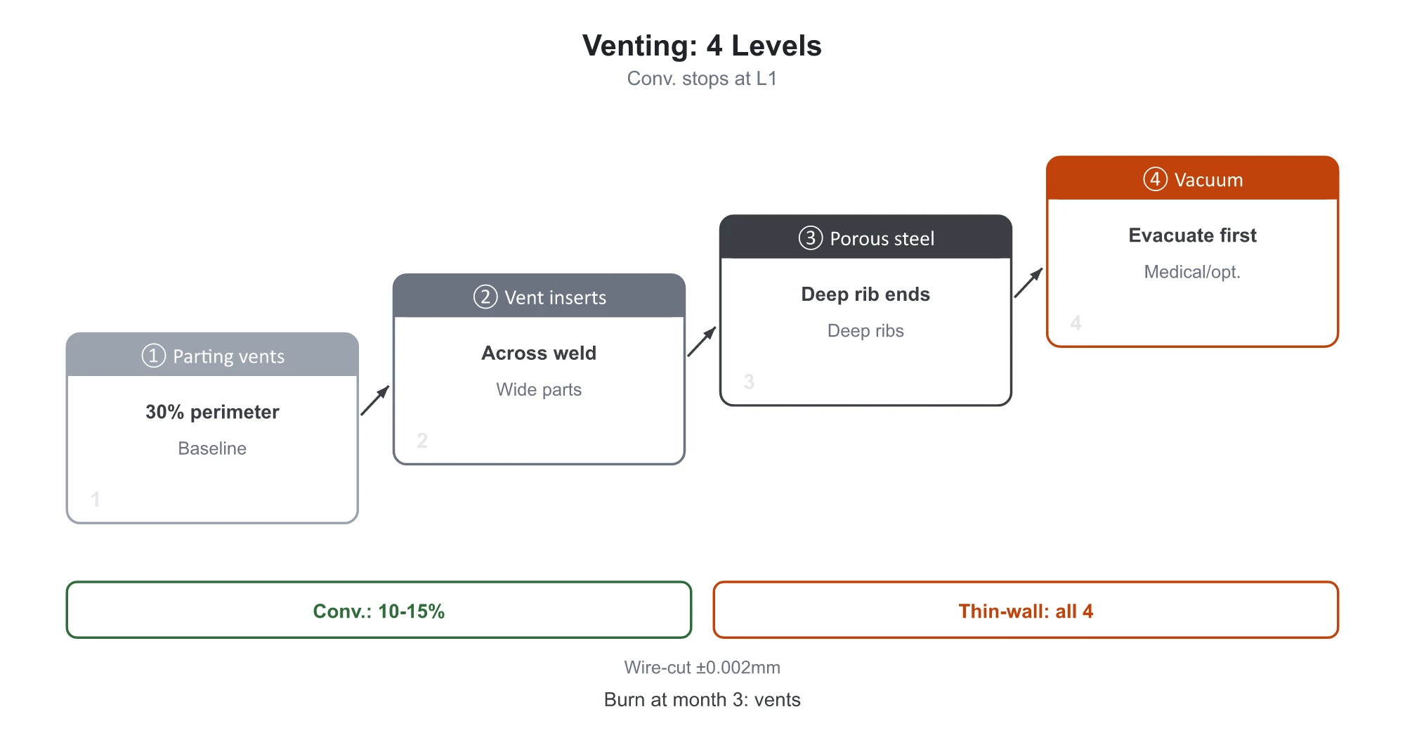
Venting also requires active maintenance. Vent slots need cleaning every two to four weeks. Many production lines that run cleanly on day one start experiencing daily burn marks after three months, simply because polymer volatiles and additives clog the vents. When this occurs, inspect the vents before adjusting process parameters. Lowering injection speed and pressure might reduce burn marks slightly, but it drags out cycle times and creates short shots downstream.
Inadequate venting on a conventional mold is an annoyance; on a thin-wall mold, it destroys yield rates.
Steel Selection and Structural Rigidity
When injection pressure doubles, standard mold steel is the first component to fail.
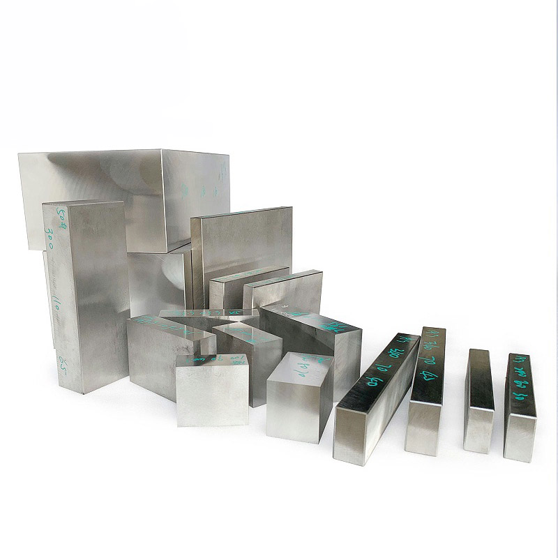
The standard tooling baseline uses pre-hardened steels like P20 or 718H at HRC 28–35 for core and cavity inserts, which reliably handles low-to-medium volumes up to 500,000 shots. Most conventional consumer appliance and automotive molds use this specification.
That baseline cannot support thin-wall molding. Cavity pressures reaching 250 MPa cause softer steels to flex elastically under load—a phenomenon known as “mold breathing.” Engineering data shows that platen or insert deflection of just a few hundredths of a millimeter (thinner than a human hair) forces the parting line open, creating flash and causing part dimensions and wall thickness to drift out of tolerance. Microscopic deflections create the most expensive production issues.
Thin-wall molds upgrade core and cavity inserts entirely to hardened tool steels, starting at HRC 48–52 (and exceeding HRC 55 in high-spec shops). High-volume parts with cosmetic requirements use through-hardened S136 for superior corrosion resistance, mirror-polish capability, and 1,000,000+ shot life. Wear components and structural cores use through-hardened H13 or S7. Beyond steel selection, mold bases require heavy reinforcement: thicker mold plates, denser support pillar grids to absorb cavity expansion forces, and a tie-bar clearance to mold plate thickness ratio kept at 2:1 or lower.
When flash appears under thin-wall high pressures, your first instinct should not be to drop injection pressure—doing so instantly triggers short shots. First inspect machine clamping tonnage and mold base rigidity. If the mold flexes, parameter adjustments cannot fix the flash. That is why reviewing the steel specification on a quotation matters: if a supplier quotes 718H for a thin-wall application, demand an explanation.
Without sufficient rigidity, even perfectly sized gates and vents will not prevent part defects.
Cooling and Ejection Differences
Once the cavity fills, two challenges remain: uniform cooling and clean part ejection.
In cooling design, standard channels follow rule-of-thumb spacing: 8–12 mm diameters positioned 1.5 to 3 times the channel diameter from the cavity surface. Thin-wall parts require much tighter proximity—water line centerlines must sit within 2x wall thickness from the cavity surface (under 2.0 mm for a 1.0 mm wall part). Because thin sections hold little thermal mass, slight temperature variations immediately cause warpage. When conventional CNC drilling cannot reach tight contours, beryllium copper inserts (which conduct heat 5 to 8 times faster than mold steel) cool hot spots, while advanced applications use 3D-printed conformal cooling channels. In addition, core and cavity circuits must have independent temperature controls, as cross-half temperature deltas remain the primary cause of part warpage.
For ejection, thin walls lack structural rigidity, and molded-in stress from high cavity pressures releases during demolding, causing stress whitening. Pin-push whitening (ejector marks) occurs over pin locations, while drag whitening develops along corners and rib roots. The root cause usually involves a small pin surface area, insufficient draft angle, and rough cavity finish acting together.
Thin-wall molds upgrade the entire ejection setup: draft angles increase to 1.5–3° (and 3–5° for deep cavities), significantly higher than standard practices. Ejector pins must be distributed evenly across rigid areas like rib intersections and boss bases, avoiding cosmetic surfaces. Blade ejectors and ejector sleeves replace standard round pins where surface contact is needed, while deep-cavity thin-wall tools integrate nitrogen gas springs for smooth, cushioned return.
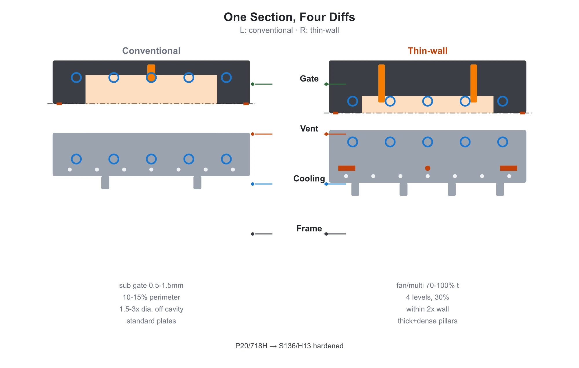
The structural differences across each subsystem are summarized below:
| Subsystem | Conventional Mold Specification | Thin-Wall Mold Specification |
|---|---|---|
| Gating System | Pin-point / single submarine gate | Fan / multi-point / sequential valve gates; gate depth = 70–100% of wall thickness |
| Venting System | Parting line slots, 10–15% perimeter coverage | 4-level venting (slots, inserts, porous steel, vacuum), ~30% perimeter coverage |
| Cooling System | Channels placed 1.5–3x diameter from cavity | Channels placed within 2x wall thickness; independent core/cavity circuits |
| Mold Steel | P20 / 718H pre-hardened (HRC 28–35) | S136 / H13 through-hardened (HRC 48–52+) |
| Base Rigidity | Standard mold plates + standard support pillars | Thickened plates, dense support pillar grid, tie-bar span to plate thickness ratio ≤ 2:1 |
| Ejection System | Standard draft angles + round ejector pins | 1.5–3° draft, blade pins / ejector sleeves placed on structural features |
This comparison table summarizes the critical structural differences and acts as an evaluation checklist when auditing tooling quotes line by line.
How to Verify a Tooling Proposal
You don’t need to be a mold designer to spot whether a supplier is offering a true thin-wall tool or repackaging a standard mold. Check these five items:
- Verify the Moldflow analysis. Experienced toolmakers can build standard molds by intuition, but cutting steel for a thin-wall mold without Moldflow simulation is a pure gamble. Moldflow plots fill time contours, air trap locations, and weld line paths. Request this report during quoting. During T1 trials, perform short-shot tests to track the actual melt front against simulation plots; discrepancies point to design or machining flaws.
- Confirm steel hardness. Thin-wall tooling calls for through-hardened tool steel rated at HRC 48+. If a supplier specifies 718H or P20, have them justify it.
- Inspect gate configuration. A single sub-gate indicates a standard mold mindset. Fan gates, multi-point entries, or sequential valve gates demonstrate thin-wall engineering.
- Evaluate venting tiers. Relying solely on parting line slots represents a conventional setup. True thin-wall proposals incorporate vent inserts, porous steel, or vacuum-assist systems.
- Define quantitative buyoff criteria. Never sign off based on initial sample parts alone. Run 100 to 300 continuous shots to evaluate dimensional stability and process capability (Cpk). Ensure your contract specifies delivery milestones, warranty shot count, and modification responsibilities in black and white.
If you encounter defects during mold trials, use this diagnostic table:
| Trial Defect | Primary Checkpoint | Can Parameter Tuning Fix It? |
|---|---|---|
| Short shots / incomplete fill | Gate dimensions, gate count, cavity venting | No, if trapped air cushions the melt, it requires mold modification. |
| Burn marks at end of fill | Vent location/area, clogged vent slots | Cleaning unclogs slots, but insufficient vent area requires mold modification. |
| Stress whitening / drag marks | Ejector contact area, draft angle, cavity polish | Polishing fixes minor dragging, but an inadequate draft requires mold modification. |
| Parting line flash | Clamping tonnage, mold base rigidity | No, if platens or cavity inserts deflect under pressure. |
Veteran mold makers share a proven rule of thumb: injection molding issues are 70% tooling, 20% process parameters, and 10% resin. Endless machine parameter adjustments only mask surface symptoms; they cannot fix structural mold defects. Bringing this checklist to discussions with mold suppliers protects you from being brushed off with “We’ll just tweak the machine settings.”
When You Must Build a Thin-Wall Mold
Follow three practical decision rules:
- Wall thickness above 1.5 mm with an L/t ratio under 100:1: Conventional tooling is completely sufficient; do not pay extra for thin-wall specifications.
- Wall thickness under 1.0 mm or an L/t ratio exceeding 150:1: You must build a dedicated thin-wall mold. Gating, venting, steel hardness, and rigidity function as an integrated system—changing only one element will not work.
- The transition zone (wall thickness 1.0–1.5 mm, L/t ratio 100–150:1): Skip the guesswork and run Moldflow simulation first to let fill analysis determine the tooling requirement.
What is the price difference? A thin-wall mold costs 10% to 40% more than a conventional mold. That premium goes directly into through-hardened steels, close-proximity cooling channels, multi-tier venting, and reinforced mold bases. If you want to optimize your tooling budget, do the math first to verify whether your part truly needs a thin-wall structure.
A thin-wall mold is not a lighter version of a standard mold—it is an engineered tooling system built for high-pressure and extreme speed. If the structural design is wrong, low initial costs and machine tuning cannot save the project. When configured correctly, the upfront investment pays for itself with trouble-free mold trials and stable, high-volume production.
At moldsteells — an Injection Mold Manufacturer — we specialize in high-precision mold manufacturing. If you have a thin-wall component under evaluation, send over your part drawings and wall thickness specifications. We will calculate the L/t ratio, run Moldflow simulations, and configure the right gating, venting, and steel grades to provide a tailored mold manufacturing solution.