Why Thin-Wall Mold Cooling Is “Short but Unstable”
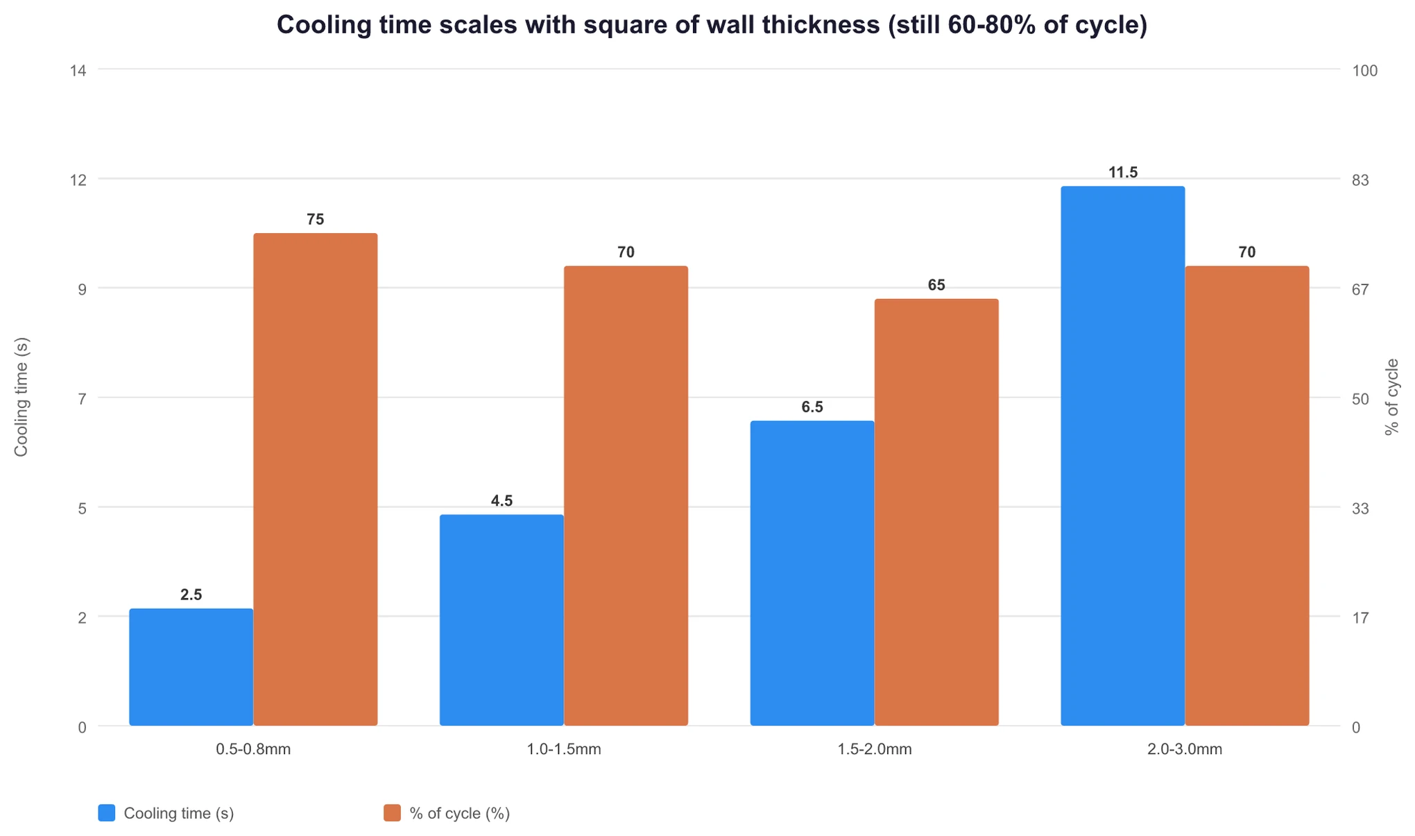
The cooling time of a thin-wall Injection Mold is short, but it still accounts for 60-80% of the full molding cycle. A shorter time does not mean it is easier to control. RJG gives 80-85%, Aco Mold gives 70-80%, and MDPI Energies 2025 places the upper limit at 80%. All three sources point in the same direction. When wall thickness drops from 2 mm to 1 mm, cooling time falls to one-quarter based on the square-law relationship in BASF’s formula, tw = const·s². Standard parts often cool in 8-15 s, while thin-wall parts are pushed into the 3-6 s range. The absolute time is cut by more than half. If a mold shop uses the same cooling layout for a thin-wall part, cooling time is where instability shows up first.
The root cause is three hard constraints stacked:
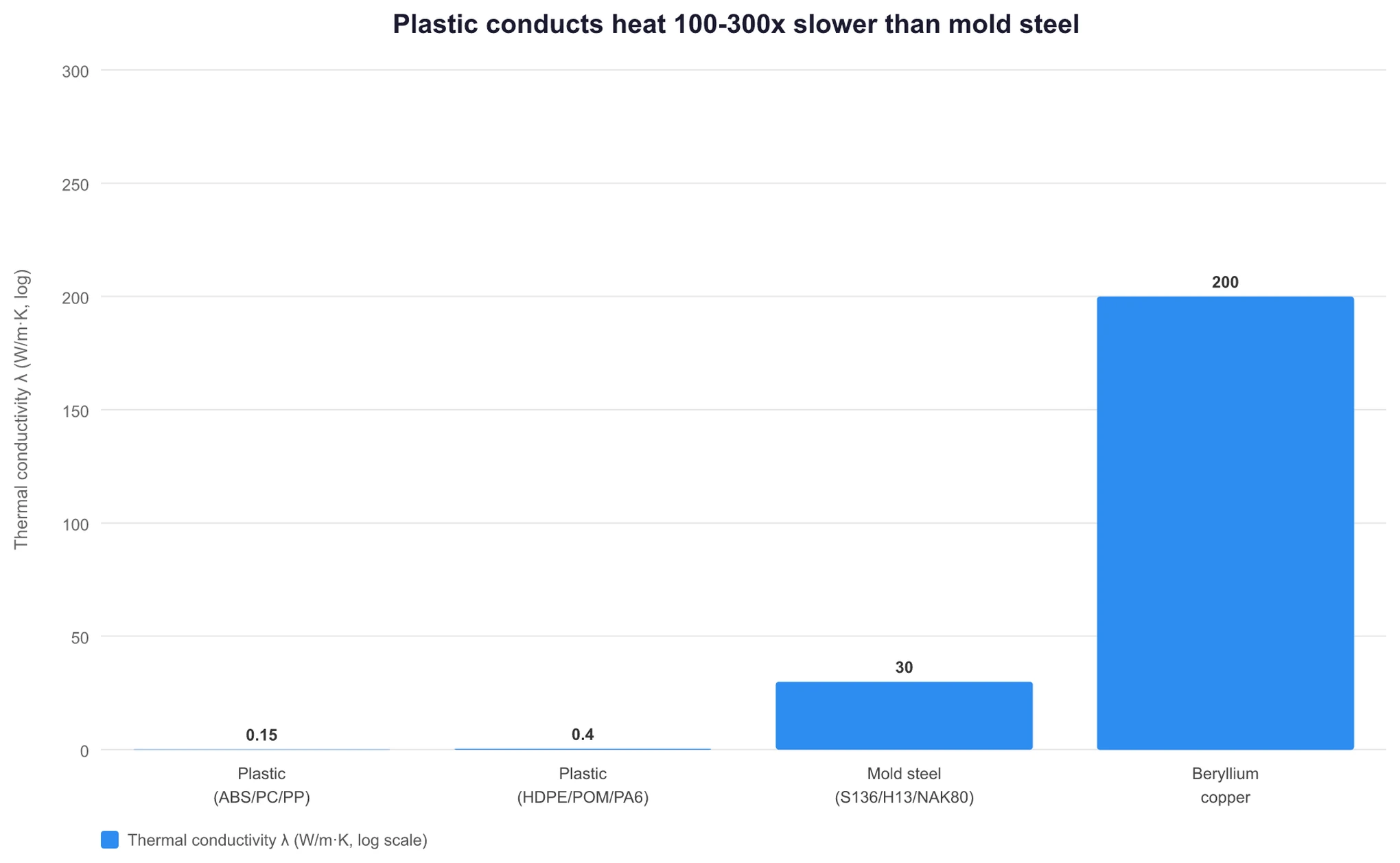
- Plastic itself dissipates heat slowly: Common plastics have a thermal conductivity, λ, of about 0.1-0.3 W/m·K. Mold steel is around 30 W/m·K, a difference of roughly 100-300 times, based on Thermtest Asia citing Lasance 2001, plus Omnexus and Professional Plastics. Plastic cools slowly. Mold steel is the material that actually carries the heat away.
- The thinner the wall, the shorter the heat path in absolute terms: The amount of heat that must be removed per unit time does not fall. Because the wall is thinner, the temperature gradient across both sides becomes steeper, which increases the heat-removal load on the mold steel.
- The cooling channels physically cannot get close enough: For thin-wall parts, the distance from the cooling-channel centerline to the cavity surface should be ≤2× wall thickness, based on CK Mold’s rule of thumb. At a 1 mm wall, that means ≤2 mm from channel center to surface. A conventional 8-12 mm drill simply cannot fit. The solution has to be conformal cooling, where the channel follows the cavity contour, or beryllium copper, BeCu, inserts.
These three constraints compress the process window of thin-wall molds into a narrow slot. Injection speed must be raised to 300-600 mm/s, versus 50-150 mm/s for standard parts. Peak cavity pressure reaches 25-35 kpsi, versus 10-15 kpsi. Fill time must be cut to under 0.5 s. LongTeam, JCProto, and FindMold all agree on this range. This means a thin-wall mold is not just a standard mold with adjusted parameters. It requires a different approach in design, equipment, and mold steel.
Note: There are two common definitions of thin wall. A wall thickness of ≤1.5 mm is the industry threshold, according to Team MFG. A thickness of ≤1.0 mm is the stricter geometric definition, cited by LongTeam from Kemal Mfg 2025. Process definition depends on L/t, the flow-length-to-thickness ratio. For high-flow materials such as PP and HDPE, 150:1 is the critical point. For engineering plastics such as ABS and PC, 200:1 or higher is usually where thin-wall processing requirements begin. KingStar Mold, Tstar Mold, and Syntex America all align on this.
Cooling Channel Layout: From Rule of Thumb to Hard Constraints in Thin-Wall Molds
The cooling circuit is the vascular system of the mold. Start with the standard design rules used across the industry:
| Parameter | Rule of Thumb | Source |
|---|---|---|
| Cooling channel inside diameter, D | 8-12 mm | PolySource + PMC10347042 Table 1 + Facebook TechInst |
| Center-to-center spacing | 3-4D, with some sources extending to 3-5D | ResearchGate design guide + Alpine Mold |
| Channel center to cavity surface | 1.5-3D | PolySource + PMC10347042 |
| Reynolds number, Re | >4000, with 6000-8000 recommended | Moldex3D + Autodesk Moldflow + Plastics Technology |
These rules work for standard molds. In thin-wall molds, two harder constraints lock them down:
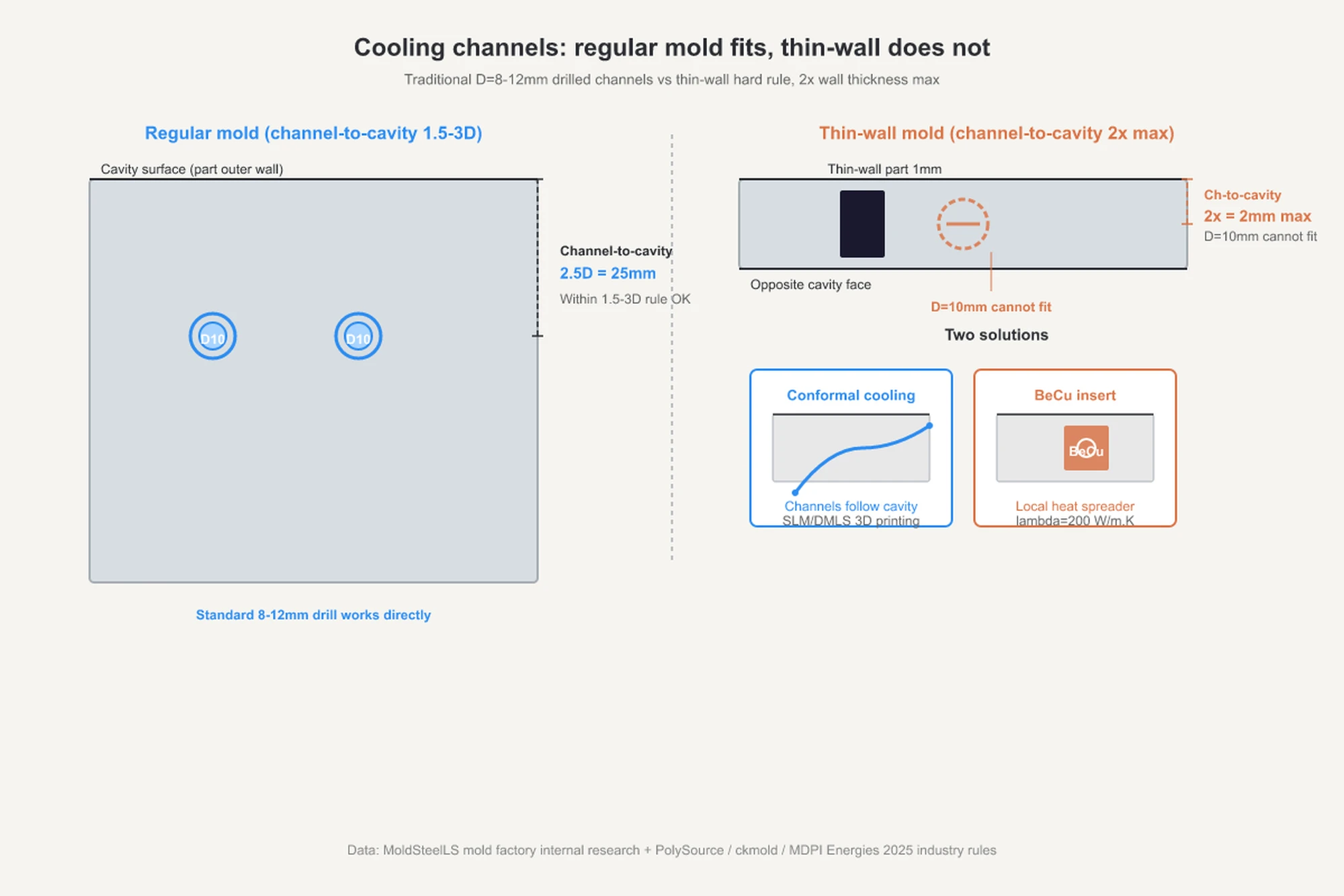
- Channel center to cavity surface ≤ 2× wall thickness, based on CK Mold’s design rule. At a 1 mm wall, the distance must be ≤2 mm. Conventional 8-12 mm drilling cannot achieve this. The options are conformal cooling or BeCu inserts.
- Temperature difference between the cooling channel and cavity surface ≤2 °C, based on PTI.tech and MDPI Energies 2025. Once the difference exceeds 2 °C, warpage rises sharply. This is the main driver of dimensional distortion in thin-wall parts.
Why highlight Re > 4000 on its own? Under laminar flow, heat-transfer efficiency is several times lower than under turbulent flow. A quick engineering reference makes the point clear. In a 10 mm channel with water at 2 m/s, Re is about 17,000, well above the 4000 threshold. At 0.4 m/s in the same 10 mm channel, Re drops below 4000, and cooling efficiency can be cut in half. Mold designers need to calculate this number during the cooling design stage.
Why is channel spacing set at 3-4D? If channels are too close, cooling becomes more uniform, but machining costs rise sharply. If they are too far apart, cooling becomes uneven, and the part distorts after ejection. The 3-4D range is the industry balance point. Alpine Mold gives 3-5D, while PolySource and the PMC paper give 3-4D. The more conservative 3-4D range is the safer choice.
Why Mold Steel Also Needs an Upgrade
The extreme processing conditions of thin-wall parts, 25-35 kpsi cavity pressure and fill time under 0.5 s, act directly on the mold steel. P20 is the workhorse steel for standard molds, but it is not enough for thin-wall applications with high structural demands. P20 lacks adequate bending strength. Under injection pressure, the mold can elastically deform by about 0.025 mm. In shop terms, this is called mold breathing. In thin-wall parts, that deformation can lead to flash, according to both LongTeam and CK Mold.
The upgrade path usually has three levels:
| Steel Grade | Typical HRC | Application | Source |
|---|---|---|---|
| H13 | 48-52 | General-purpose high-strength thin-wall molds | LongTeam + Custom Plastic Moldings |
| S7 | 54-58 | High-impact thin-wall parts | Custom Plastic Moldings + Spark Mould + ZetarMold |
| S136 | 48-52 | Thin-wall parts with high-gloss or mirror finish | moldsteells records, thin-wall mold steel specifications |
| NAK80 | 37-43, pre-hardened | Thin-wall parts with high gloss and medium-volume production | Widely used in the industry; moldsteells records, same thin-wall mold steel section |
moldsteells can consistently produce S136 and NAK80, as stated in its records on thin-wall mold parameters. These are standard choices for thin-wall, high-gloss projects.
Upgrading steel increases mold cost, but it is necessary. Under the high cavity pressure of thin-wall molding, P20 can deflect by 0.001 in, or 0.025 mm, and ruin a production lot. The cost impact is far greater than the steel upgrade itself.
Conformal Cooling vs. BeCu Inserts: How to Run the Cost-Benefit Comparison
When a standard mold shop cannot get cooling close enough for a thin-wall part, there are usually only two options: conformal cooling and BeCu inserts. The trade-off in benefit and cost is straightforward.
Benefit of conformal cooling: Based on multiple sources, PTI.tech at 10-40%, MDPI Energies 2025 CFD test at -18.7%, PatSnap review at 30-63%, Xometry at 30-50%, and Castman review up to 70%, a conservative range is a 10-40% reduction in cooling time. The most cited real-world case is Renishaw’s redesign of the Kärcher K2 pressure-washer housing mold with conformal cooling. Cooling time dropped from 22 s to 10 s, a 55% reduction. Total cycle time dropped from 52 s to 37 s, a 29% reduction. Wall temperature dropped by 40-70 °C. Renishaw’s original case confirms all three figures. Renishaw adopted conformal cooling to meet an expanded output target of 12,000 parts per day. This was not a process tweak. It was a capacity requirement.
Benefit of BeCu inserts: Beryllium copper, such as grades C17200 and C17510, has a thermal conductivity of 180-250 W/m·K. That is on the order of 1000 times higher than plastic, according to Thermtest Asia, Autodesk, and Nature 2025. Used as local heat sinks inserted into hot spots, BeCu has a relatively low mold-modification cost per part. But it only solves local cooling problems. Uniform cooling across the full mold still depends on conformal channel design.
Cost range: By common industry experience, including additive-manufacturing routes, conventional cooling adds no extra cost; BeCu inserts typically increase mold cost by about 5-15% per tool; a 3D-printed nickel-alloy steel core with conformal cooling, such as Renishaw’s SLM or DMLS process, typically increases mold cost by about 30-80% per tool. This is an industry experience range rather than a value backed by independent quantified sources, so it should be treated as a rule of thumb.
How to choose: If the part has three or fewer critical hot spots, BeCu inserts are usually more cost-effective. If hot spots are spread across the part, or the wall thickness is ≤1 mm over a large area, conformal cooling is necessary.
Conformal cooling does not mean a 3D-printed mold. This is a common industry misunderstanding. Conformal cooling is the result, a cooling path that follows the cavity contour. It can be achieved by a 3D-printed mold core using SLM or DMLS, by a hybrid layout that combines BeCu inserts with conventional drilled channels, or by curved channels milled with special tooling. 3D printing is only one process route.
Note: Conformal cooling is not the same as RHCM, rapid heat cycle molding, for high-gloss molds. Conformal cooling solves uneven cooling and long cycle time. RHCM uses steam or hot water to switch mold temperature and improve surface gloss. The first is a cooling-efficiency issue. The second is a surface-quality process. They are entirely different process paths.
Is It Worth Moving Moldflow Simulation Up Front?
This is the step buyers most often skip, and one that mold shops rarely bring up on their own.
There is a common number in the industry: about 40% of thin-wall part defects can be traced back to wall-thickness design errors. LongTeam cites SilkBridge 2025, while EvokPoly cites Fictiv, and ZetarMold reaches the same conclusion independently. The remaining 60% are split between gate and runner design, which drives weld lines and burning, and cooling-system design, which drives warpage and sink. Most of these problems can be eliminated during DFM, design for manufacturability, if someone runs the simulation first.
The cost comparison between front-loaded simulation and T1-stage correction, based on LongTeam engineering experience, looks like this:
- Front-loaded approach: Before cutting steel, use Moldflow, Autodesk’s flow-simulation software, or equivalent platforms such as Moldex3D or Cadmould 3D-F, to simulate fill time, weld lines, air traps, uneven cooling, and warpage distribution. If there is a problem, revise the 3D data. The correction cost is zero.
- T1-stage correction: Based on LongTeam engineering experience, changing one gate location or one cooling path at T1 typically adds $8,000-$25,000 in mold cost and delays the program by 4-6 weeks. This is an experience-based figure rather than one backed by an independent quantified source. Autodesk only supports the point qualitatively by noting that simulation helps avoid rework cost.
Using LongTeam’s numbers for a sensitivity check: if one project carries a mold cost of RMB 300,000 and a profit of RMB 80,000, then one T1 correction that causes a four-week delay during the market window and adds about $15,000 in cost (roughly RMB 110,000) can wipe out the whole order’s profit. A Moldflow simulation usually costs only about one-tenth of a mold rework, and the timing difference is roughly four weeks versus two days.
Moldflow is not the only platform. Autodesk Moldflow, CoreTech System’s Moldex3D, and Simcon’s Cadmould 3D-F are the three mainstream options today. All can cover filling, cooling, and warpage. The practical choice depends on which software the engineer knows best.
In moldsteells’ process, Moldflow analysis is a required step after the DFM review, not an option, as stated in its project workflow records. On the processing side, the company uses 90-260 ton injection molding machines, suitable for thin-wall parts with wall thickness from 1-3 mm, plus one fine-hole EDM machine, Xiufeng CNC3545, which can support basic cooling-path work for conformal-cooling layouts. For thin-wall molds, front-loaded simulation, cooling-channel design, and machine tonnage have to work together.
The Acceptance Checklist for Thin-Wall Molds: Match These 4 Items and Cooling Becomes Stable
Here is a practical four-step acceptance checklist for customer engineers, based on industry experience and supported across PTI.tech, MDPI, CK Mold, and PolySource:
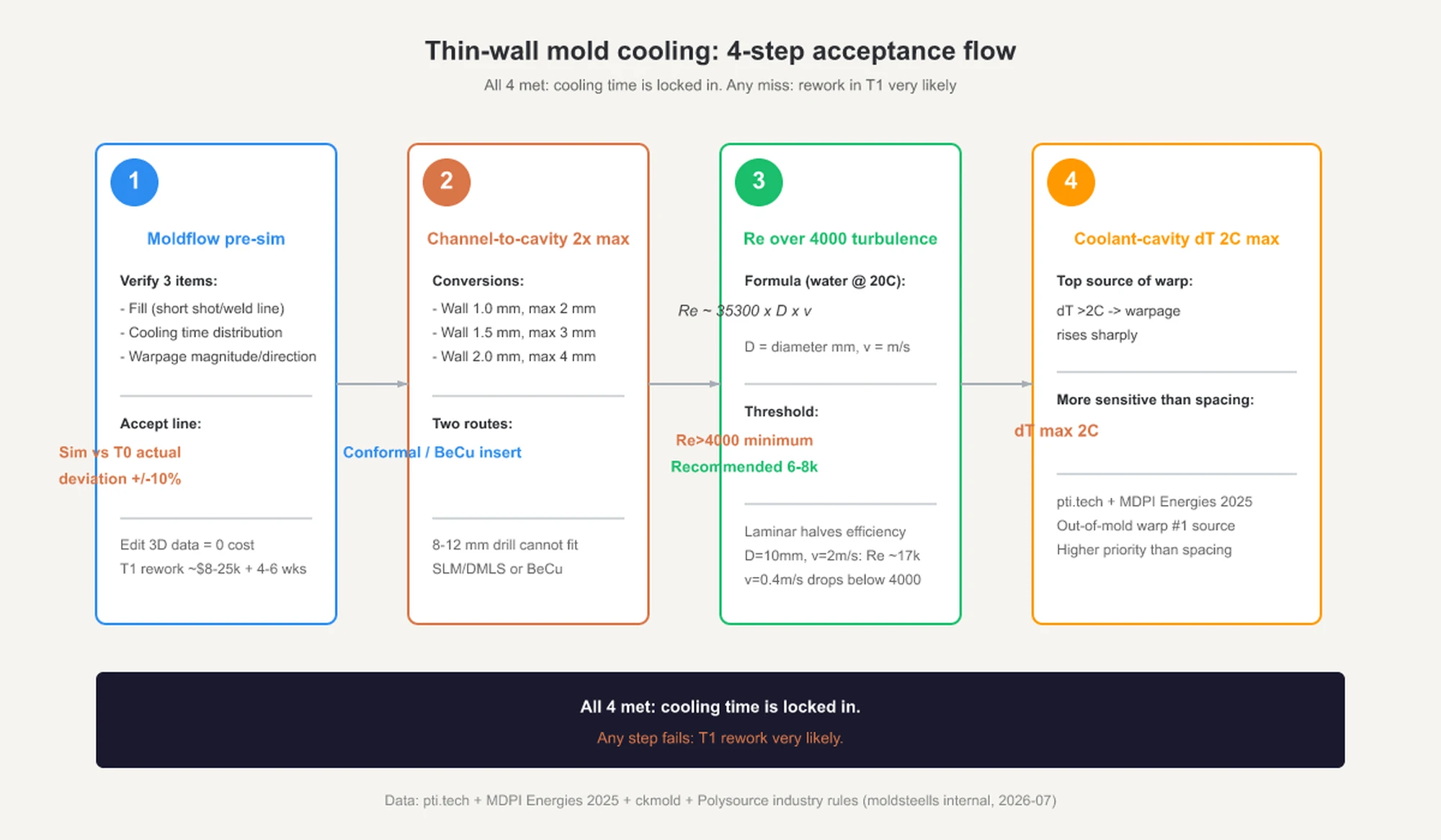
- Run Moldflow simulation up front: Verify filling, short shot, weld line, and air trap; cooling, time distribution, and temperature gradient; and warpage, including deformation amount and direction. The deviation between the simulation report and T0 trial data should stay within ±10%.
- Channel center to cavity surface ≤2× wall thickness: For a 1 mm wall, the limit is ≤2 mm. For a 1.5 mm wall, it is ≤3 mm. If that distance cannot be achieved, switch to conformal cooling or BeCu inserts.
- Turbulent flow in cooling channels, Re > 4000, with 6000-8000 recommended: Use D, channel diameter in mm, and v, velocity in m/s, to estimate Re ≈ 35300 × D × v for water at about 20 °C. If Re is below 4000, send it back for rework. Cooling efficiency can drop by more than half.
- Temperature difference between cooling channel and cavity surface ≤2 °C: Once the difference exceeds 2 °C, warpage rises sharply. This is the leading source of post-ejection distortion and is even more sensitive than channel spacing.
If all four items line up, cooling time is usually stable. If any one of them does not, there is a high chance the mold will need correction at T1.
Appendix: Wall Thickness × Cooling Time Reference Table for thin-wall molds under standard processing conditions, for checking only:
| Wall Thickness | Cooling Time | Share of Cycle Time | Hard Limit for Channel-to-Surface Distance |
|---|---|---|---|
| 0.5-0.8 mm | 2-3 s | 70%+ | ≤1-1.6 mm, conformal cooling, or BeCu required |
| 1.0-1.5 mm | 3-6 s | 65-75% | ≤2-3 mm, conformal cooling needed in most cases |
| 1.5-2.0 mm | 5-8 s | 60-70% | ≤3-4 mm, conventional channels are barely feasible |
| 2.0-3.0 mm, upper range for standard molds | 8-15 s | 60-80% | 1.5-3D, the standard range for conventional cooling channels |
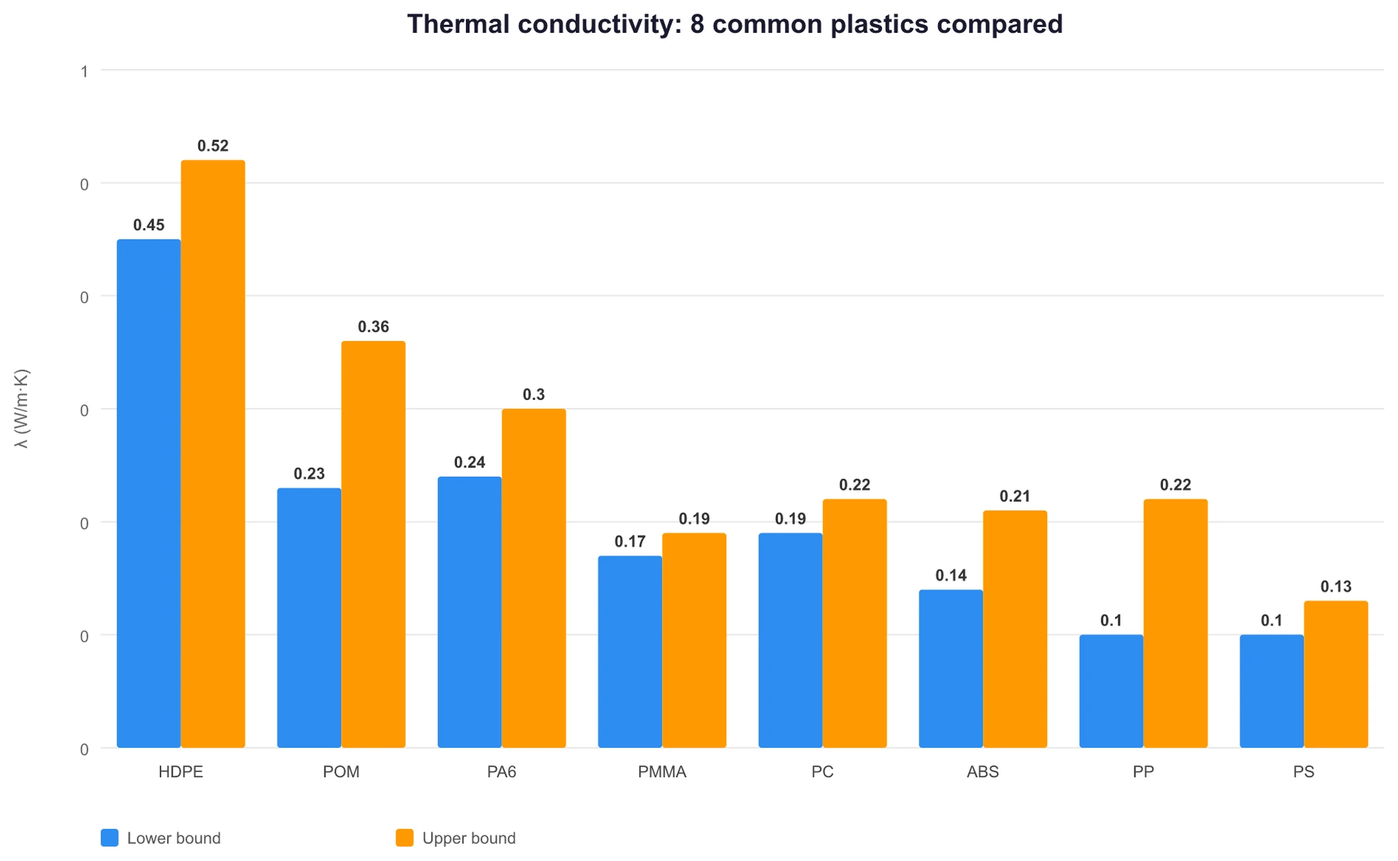
Appendix: Quick Reference for Thermal Conductivity of Common Plastics, from Thermtest Asia, citing Lasance 2001:
| Material | Thermal Conductivity λ, W/m·K | Suitability for Thin Walls |
|---|---|---|
| ABS | 0.14-0.21 | General-purpose; MFR ≥30 required |
| PC | 0.19-0.22 | Moderate flow; high-MFR modified grades needed for thin walls |
| PA6 | 0.24-0.30 | With glass fiber, conductivity rises to 0.36-0.5, a 1.5-2× increase, based on BASF Ultramid B3EG6 datasheet values |
| POM | 0.23-0.36 | Relatively weak flow; use with caution in thin walls |
| PP | 0.1-0.22 | Best flow; most suitable for ≤0.6 mm thin walls |
| HDPE | 0.45-0.52 | Good flow and highest conductivity; preferred for thin walls |
| PS | 0.1-0.13 | Good flow but brittle; often used in thin-wall packaging |
| PMMA | 0.17-0.19 | Common in optical parts; watch for stress cracking in thin walls |
Trade-off with glass-fiber reinforcement: 30% GF ABS has a flexural modulus of 5.8-6.9 GPa, based on Oxford Polymers at 5.86 GPa and eFunda at 6.9 GPa, versus about 2.0 GPa for neat ABS, nearly a threefold increase. HDT rises from 80 °C to 104-109 °C. Stiffness and heat resistance both improve, but flow gets worse and anisotropic shrinkage increases, which means more warpage. In thin-wall parts, that trade-off needs to be evaluated carefully.
FAQ: The 7 Most Common Questions About Thin-Wall Mold Cooling
Q1: Does cooling time in thin-wall molds really account for 60-80% of the cycle?
Yes. Multiple sources place it in the 60-80% range: RJG at 80-85%, Aco Mold at 70-80%, EvokPoly at 60-80%, and MDPI Energies 2025 with an upper limit of 80%. Thin-wall parts have short cycles, so absolute cooling time may be compressed to 3-6 s, but its share of total cycle time can be even higher. Improving cooling is one of the most direct ways to reduce cycle time.
Q2: If thinner walls cool faster, why are they harder to control?
Cooling time falls with the square law, tw = const·s², but the hard limit for channel-to-surface distance also shrinks with wall thickness. At 1 mm wall thickness, the cooling-channel center must be within 2 mm of the cavity surface. A conventional 8-12 mm drill cannot fit there. That means conformal cooling or BeCu inserts become necessary, and both equipment requirements and mold costs move up to the next level.
Q3: Does conformal cooling always require a 3D-printed mold?
No. Conformal cooling is the result, cooling channels that follow the cavity contour. There are three implementation routes: a 3D-printed mold core using SLM or DMLS additive manufacturing, a combination of BeCu inserts and conventional drilling, or curved cooling paths milled with special tools. 3D printing is only one of these routes.
Q4: Beryllium copper is toxic. Are mold shops willing to use it?
BeCu is widely used in solid-form operations such as machining, milling, and insert assembly under standard industrial hygiene controls, including wet cutting, ventilation, and personal protective equipment. This is normal practice in the industry. Mainstream BeCu grades such as C17200 and C17510 have mature processing know-how. The primary risk is inhalation of dust during processing. A solid insert used inside the mold itself is safe in service.
Q5: How much does front-loaded Moldflow simulation cost?
Simulation services are priced by project complexity. For a single thin-wall part, the market range is usually a few thousand to around ten thousand RMB, depending on the supplier and scope of service. Compared with T1 mold rework, which LongTeam engineering experience places at $8,000-$25,000 plus 4-6 weeks, simulation cost is roughly one-tenth as much.
Q6: What types of thin-wall parts can moldsteells make?
Its records state that it can build thin-wall molds. According to the listed thin-wall mold parameters, 90-260 ton injection molding machines are suitable for thin-wall parts with wall thickness from 1-3 mm. One Xiufeng CNC3545 fine-hole EDM machine is available for basic cooling-path work related to conformal cooling. Moldflow analysis is a required step after DFM review. On the mold-steel side, S136 and NAK80 are standard choices for thin-wall, high-gloss work. If a thin-wall part drawing is available, the 3D file and material list can be reviewed to determine the cooling concept during the DFM stage.
Q7: Are thin-wall molds the same as RHCM high-gloss molds?
No. A thin-wall mold is for injection-molded parts with wall thickness ≤1.5 mm or L/t >150:1, where the core problem is getting the cooling channels close enough to the cavity. A high-gloss mold using rapid heat cycle molding relies on steam or hot water to switch mold temperature quickly, typically from 80 °C to 200 °C, to eliminate surface weld lines and improve gloss. The process route, equipment setup, and cost structure are different. Conformal cooling solves the first problem. A steam-based RHCM system solves the second. They should not be treated as the same thing.