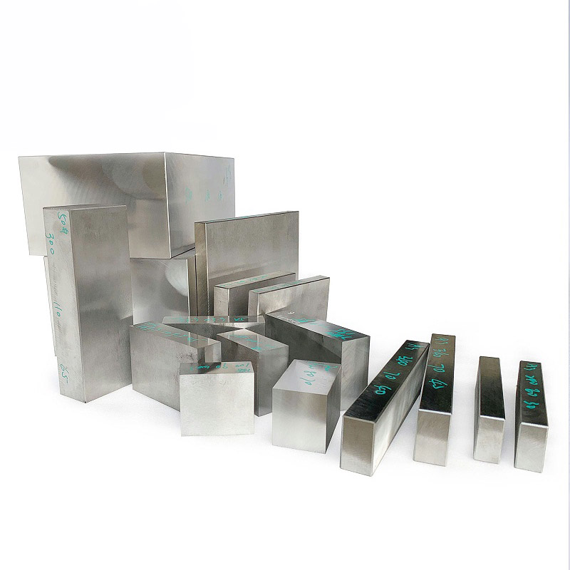
Charger housing molds are fundamentally different from standard plastic injection molds. Flame retardancy, thin walls, and high-volume output create a three-way engineering challenge. These are not separate problems that can be solved one by one. They interact as one system.
H13 steel works well for ordinary plastic molds. But when it is used for charger housings molded in V0 flame-retardant PC/ABS (FR = flame retardant; V0 = the highest vertical burn rating, not standard PC/ABS alloy), the cavity surface starts to pit after only tens of thousands of cycles. This is not wear damage. It is a chemical attack from acidic gases released when the flame retardant decomposes at high temperature.
This article breaks the issue into three parts: how to choose the steel, how to control the process window, and how to keep mass production stable.
How Charger Housing Molds Differ From Standard Injection Molds
Most standard plastic molds mainly deal with one priority at a time: dimensional accuracy, surface appearance, or output. Charger housing molds have to handle all three at once. The material is V0 flame-retardant PC/ABS; the mainstream wall thickness is 0.8 to 1.0 mm, and annual output often starts at 1 million parts. These are not independent choices. A affects B, B affects C, and C feeds back into A.
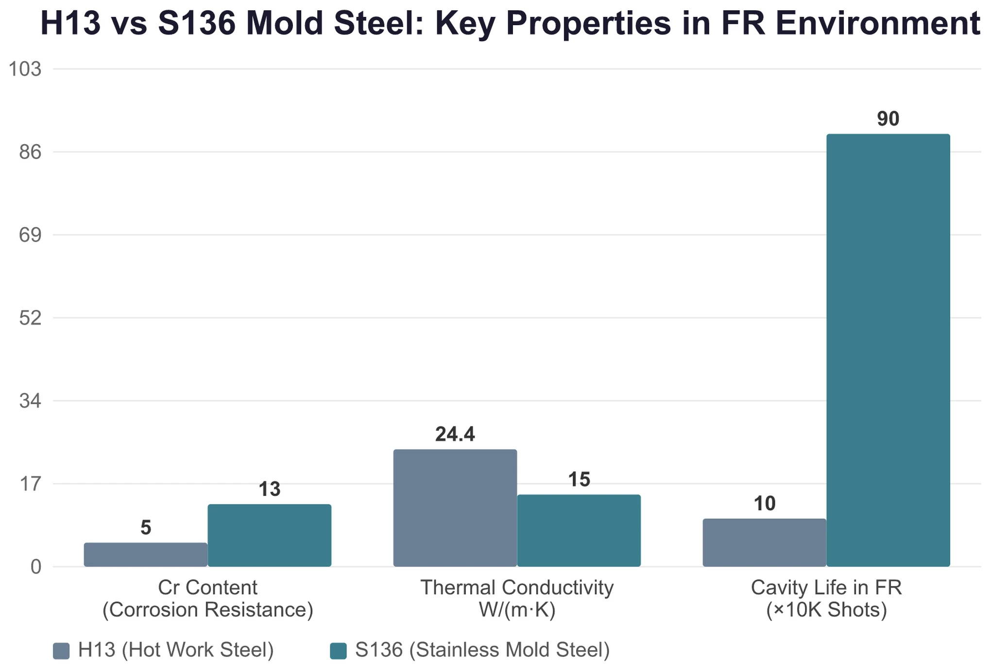
When flame-retardant resin is molded above 280 °C, brominated flame retardants decompose and release hydrogen bromide. When it meets moisture, it forms hydrobromic acid. That means every cycle exposes the cavity surface to a small burst of acid mist. Standard H13 mold steel contains only about 5% chromium. It cannot withstand this continuous chemical corrosion, so the cavity surface develops pits after tens of thousands of shots.
Thin wall design adds another limit. The recommended wall thickness for PC/ABS is 1.5 to 3.0 mm. A charger housing at 0.8 mm is already at the edge of the material’s flow limit. If injection speed is too low, the part short-shots. If it is too high, the flame retardant decomposes. If mold temperature is too low, the melt will not flow. If it is too high, silver streaks appear. The process window is razor-thin.
High volume adds the third constraint. If annual output is 1 million parts, the mold needs a service life of at least 500,000 cycles, equivalent to SPI Class 102 or above. A weak point in the cooling system or a small imbalance in a multi-cavity runner can build up thermal stress over hundreds of thousands of cycles and create microcracks in cavity ribs.
These three pressures are constraints inside the same system. One-dimensional optimization will fail. Steel selection must resist corrosion from flame-retardant resin, transfer heat fast enough for thin-wall cooling, and still reach the hardness needed to survive up to 1 million cycles. The sections below break this down step by step.
The Resin Is Eating Your Steel: Steel Selection and Venting Design
When a cavity fails in a flame-retardant mold, is it worn out or chemically attacked? The answer is chemical attack.
When brominated flame retardants see melt temperatures above 280 °C, they release hydrogen bromide. In the presence of moisture, this becomes hydrobromic acid. In practical terms, each injection cycle sprays a trace of acid onto the cavity surface. Chlorinated flame retardants are even less thermally stable and break down earlier. Phosphorus-based systems are better, but venting still matters. This is a corrosion issue, not something that better wear resistance can solve.
That is why the cavity side, or A-side, must use stainless mold steel. S136 (ASSAB grade Stavax ESR, a martensitic stainless mold steel with 12% to 14% chromium) is the standard choice for charger housing cavity surfaces. After hardening to HRC 48-52, it can be polished to an SPI A1-A3 mirror finish. H13 hot-work tool steel has a thermal conductivity of about 24.4 W/(m·K), roughly 50% higher than S136 at about 16 W/(m·K). Even so, H13 should not be used on the cavity surface. Its chromium content is only about 5%, so flame-retardant decomposition gases will pit it after tens of thousands of cycles. Once pitting starts, every shot worsens it. Surface roughness on the molded part increases, and repair costs quickly exceed the steel price difference. A hybrid approach works better: use S136 stainless steel on the cavity side for corrosion resistance and H13 on the core side. The core side does not directly face the acidic gas, so it can benefit from H13’s faster heat transfer and shorten cooling time.
Beryllium copper is often used under thin-wall areas as an insert material, usually C17200, to improve heat transfer. That is standard practice in the mold industry. But beryllium copper should not be used in molds for flame-retardant materials. The flame retardant can react chemically with the beryllium copper. The result is part discoloration, and the insert can fail after only a few production runs. A better option is a stainless-steel insert with a CrN coating (chromium nitride, 2 to 5 microns thick). This improves corrosion resistance and release performance—effectively adding a protective chemical barrier to the cavity surface.
On flame-retardant molds, vent grooves need to do two jobs at the same time. They must release trapped air to prevent burning, and they must also discharge decomposition gases from the flame retardant to reduce corrosion. For V0 flame-retardant PC/ABS, the minimum main vent depth is 0.03 mm. Standard PC/ABS vents usually range from 0.025 to 0.038 mm. Why is the flame-retardant grade set so tightly at 0.03 mm? Too deep causes a flash. Too shallow leads to burning and corrosion. Vent width should be 5 to 10 mm, with a length of 3 to 5 mm extending to the mold edge. Add porous steel inserts in areas with serious gas trapping. The venting system is the first line of defense in flame-retardant molds. It cannot be treated casually.
At 0.8 mm wall thickness, fill depends on Three Parameters
The recommended wall thickness for PC/ABS is 1.5 to 3.0 mm. A charger housing at 0.8 mm is already operating at the boundary of thin-wall injection molding. Below 0.8 mm, a high-flow PC/ABS grade is mandatory, with MFR above 20. MFR is melt flow rate, and a higher number means better flowability. Without that, short shots are almost inevitable. PC alone cannot reliably reach this thickness. Its practical lower limit is about 1.0 mm. Below that, flow becomes difficult, and short-shot risk rises sharply. PC/ABS can be pushed down to 0.8 mm because the ABS phase improves flow.
Whether a thin wall can fill depends mainly on three parameters.
First is injection speed. Standard PC/ABS usually fills at 80 to 100 mm/s. Thin-wall charger housings need more than 200 mm/s, which means the injection molding machine must have an accumulator. Older machines without one cannot reach the required speed. If the part does not fill, that is not a process-tuning issue. It is a hardware limitation.
Second is mold temperature. For opaque charger housings, mold temperature should stay between 80 and 100 °C, and around 85 °C is a common stable range. Below 80 °C, the melt does not flow well, and filling becomes incomplete. Above 100 °C, PC/ABS is prone to silver streaks, and flame-retardant decomposition accelerates.
Third is injection pressure. Thin-wall parts need 140 to 180 MPa. The normal 120 MPa range is not enough. Once pressure goes up, corrosion resistance requirements for the screw and barrel also increase. Flame-retardant decomposition gases also attack the inside of the barrel. A machine that has processed flame-retardant resin should ideally use a dedicated screw and barrel. It should not alternate with standard materials, because cross-contamination can damage both.
The switchover from filling to packing directly affects weight consistency in thin-wall parts. Switchover based on screw position—changing to holding pressure when the screw reaches 3 to 5 mm remaining stroke—can work on parts with uniform wall thickness. But on a 0.8 mm thin-wall part, even a small wall variation can make the switchover too early or too late. Too early leads to shrinkage. Too late raises gate stress and can even cause flash. A cavity pressure sensor switches based on actual cavity pressure, so wall-thickness variation does not shift the timing. It is like reading a thermometer instead of setting an alarm clock. When multi-cavity molds move from position-based switchover to closed-loop cavity pressure control, inter-cavity weight consistency and reject rate both improve significantly. This has already been proven in production. Before changing parameters, confirm that the switchover method itself is correct.
There is another hard limit in the process window for flame-retardant resin. Melt temperature must be about 15 °C lower than the non-flame-retardant version of the same grade, and residence time in the barrel should be cut by 30% to 40%. Every extra minute in the barrel means more flame-retardant decomposition. Back pressure should be kept low, 25 to 50 psi, or about 0.17 to 0.35 MPa. Screw speed should stay at 60 to 100 rpm, and the cushion should be 3 to 6 mm. Too little cushion can cause yellowing. Too much means the melt stays too long and starts to decompose. Flame-retardant PC/ABS must be dried at 120 °C for 4 hours before molding. These materials absorb moisture more readily than standard grades. If drying is incomplete, the molded parts will come out covered with silver streaks.
Before tool kickoff, run a Moldflow analysis to identify gas traps, shrinkage risk, and filling balance during the DFM stage. Mold manufacturers with Moldflow capability, including moldsteells, usually mark these risks directly on 3D screenshots in the DFM report. That makes it easy to compare the report with the part and spot the issues before T0 sampling instead of discovering them during trial runs.
What 1 Million Cycles Really Means: Mold Life and Cooling in High-Volume Production
An annual volume of 1 million parts is not just a rough target. SPI mold classification defines clear levels. Class 101 means well over 1 million cycles without major repair, using hardened steel, hot runners, and maximum wear resistance. Class 102 means 500,000 to 1 million cycles with fully hardened steel and optimized cooling. Class 103 covers only 100,000 to 500,000 cycles. For a charger program at 1 million parts per year, Class 102 is the minimum. Class 101 is the better target.
P20 pre-hardened steel may need parting-line repair after about 300,000 cycles, and replacement becomes likely around 500,000. That is not enough for an annual output of 1 million parts. S136 hardened to HRC 48-52 can normally handle 800,000 to 1 million cycles in a flame-retardant environment with proper maintenance. But choosing the right steel is only the start. The cooling system determines whether the mold can actually survive to that number.
If cooling is uneven, thermal stress accumulates in thin-wall ribs over time, and the cavity can crack after hundreds of thousands of cycles. The standard spacing between cooling channels and the cavity surface is 8 to 12 mm. The temperature difference between the cooling water inlet and outlet should stay within 3 °C. If the layout space is too limited in a high-volume mold, conformal cooling inserts made by 3D printing are an option. They can cut cooling time by 10% to 20% and also improve thermal uniformity. Cooling water quality is easy to overlook. The water must be filtered and softened to prevent scale. Once scale builds up inside the channels, heat transfer efficiency drops sharply, thermal fatigue accelerates, and mold life can be cut by more than half.
For S136 hardened steel to deliver 800,000 to 1 million cycles, maintenance must keep pace. Clean the parting line and vent grooves regularly based on cycle count, and check that the cooling channels remain clear. If the cavity surface uses a CrN coating, 2 to 5 microns thick, inspect the coating after 500,000 to 600,000 cycles. Once the coating wears through, the steel is exposed to acidic gas. Nitriding is another anti-corrosion option. Gas nitriding with a case depth of 0.15 to 0.30 mm and surface hardness above 900 HV can help, but the layer is still limited in depth. Once the mold approaches or exceeds 1 million cycles, regular inspection is still necessary.
When the Three Pressures Collide: Conflicts and Tradeoffs in Real Projects
Real charger mold projects do not solve problem A first and then problem B. All three constraints fight each other inside the same system.
The most typical conflict is the hot runner. A hot runner has clear benefits. It eliminates sprue waste, shortens cycle time, and improves filling balance in multi-cavity molds. But it can also create problems with flame-retardant materials. The longer the flame retardant stays in a hot manifold, the more it decomposes. Local overheating can cause decomposition byproducts to block the nozzle. Most flame-retardant grades do not recommend hot runners. If a hot runner must be used, three conditions are mandatory: external heating rather than internal heating, independent PID temperature control for each nozzle, and written confirmation from the material supplier on the flame-retardant system’s thermal stability. If those conditions are not met, a cold runner is the safer choice. A cold runner creates one extra sprue per cycle and adds a regrind step. That is still better than having the manifold clog and scrapping the whole mold three months later.
The second conflict is thermal conductivity versus corrosion resistance. S136 has strong corrosion resistance, but its thermal conductivity is only about 60% of H13. That means cooling cycles are longer. The mixed-steel approach, S136 on the cavity side and H13 on the core side, only works if the parting line seals well enough to keep flame-retardant decomposition gas from leaking to the core side. Slides and angled lifters can be coated with another CrN layer to further block corrosion paths. That helps both corrosion resistance and release.
The third conflict is cavity count versus consistency. An 8-cavity mold raises output and lowers tool cost per part, but the difficulty of runner balancing increases sharply. Deviation between cavity pressure sensor readings should stay within ±3% or within ±1.5% for precision programs. Valve pin opening-time variation on valve-gated hot nozzles should be within ±0.05 seconds. Flow imbalance means some cavities fill completely while others short-shot. Clamp force also matters. A machine below 260 tons may not provide enough clamp force for an 8-cavity charger mold. Sampling and optimization on an 8-cavity tool can take more than twice as long as on a 4-cavity tool. Leave at least two weeks between T0 and T1 to modify venting and runner details as needed. Do not compress the schedule blindly.
What Buyers Should Check on a Quotation: Key Evaluation Points
For a 4-cavity charger mold, market quotations can range from RMB 50,000-60,000 to RMB 180,000. At an exchange rate of 1:6.75, that is about $7,407-$8,889 up to about $26,667. Where does the difference come from?
First, steel. A low-cost package with P20 pre-hardened steel, using a 4-cavity cold runner layout, typically costs RMB 40,000 to 70,000, or about $5,926 to $10,370. It may be acceptable for 200,000 to 300,000 cycles, but it cannot support an annual demand of 1 million parts. A mid-range setup with 718H pre-hardened steel, hardness HRC 33-38, and a semi-hot-runner system typically falls between RMB 70,000 and 120,000, or about $10,370 to $17,778. A high-spec package with S136 stainless steel and a full hot runner starts around RMB 150,000 to 180,000, or about $22,222 to $26,667. Steel itself usually accounts for only 15% to 20% of total mold cost. On a RMB 120,000 mold, about $17,778 total, the steel cost is only a little over RMB 20,000, or roughly $2,963. The real price gap usually comes from the hot runner system and precision machining hours. Imported valve-gated hot nozzles can cost RMB 25,000 to 40,000 each, or about $3,704 to $5,926 per point. With 8 nozzles, the hot runner cost alone can exceed RMB 200,000, or about $29,630.
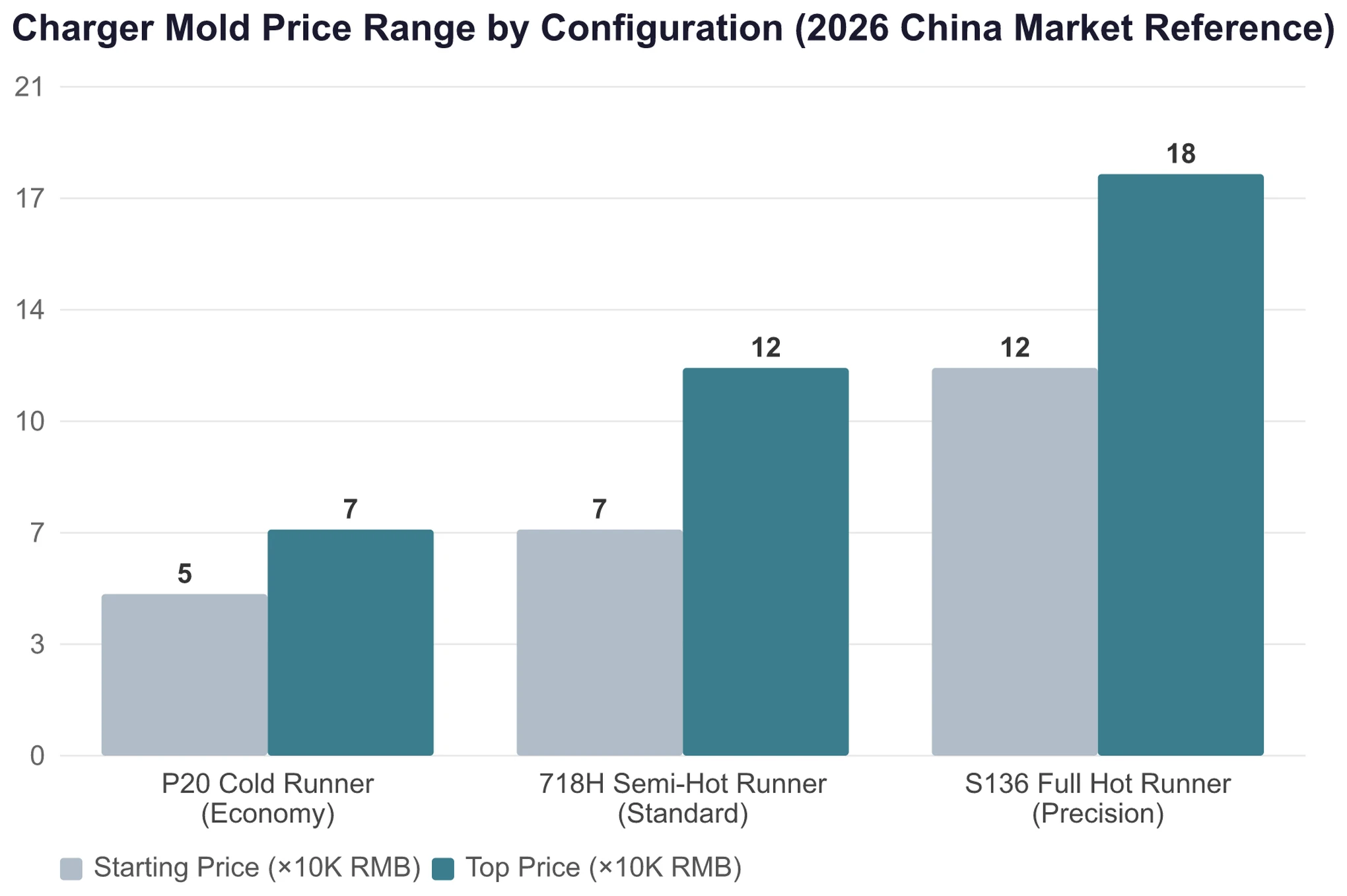
For an 8-cavity mold, a standard 718H configuration typically runs RMB 110,000 to 180,000, or about $16,296 to $26,667. An S136 high-speed precision version is usually RMB 180,000 to 280,000, or about $26,667 to $41,481. A high-end custom package can reach RMB 280,000 to 450,000, or about $41,481 to $66,667.
When reviewing a quotation, the first thing to check is the steel grade and hardness. Is the cavity surface made from S136 or an equivalent stainless grade? Is the hardened hardness specified at HRC 48-52? Is the core made from H13 or S136? If the quote mentions beryllium copper inserts, ask directly whether the supplier understands that beryllium copper should not be used with flame-retardant materials.
The second thing to check is the hot runner configuration. What brand is it? Is it valve gated or open gate? Does it have independent temperature control? If a hot runner is specified for flame-retardant resin, ask whether the supplier has confirmed compatibility with the material.
The third thing to check is the service-life commitment and mold trial plan. Look at the repair cycle between T0 and T1, the number of cycles used for continuous production validation, with 200 to 500 cycles as the industry baseline, and whether cooling water quality requirements are written into the handover documents.
At acceptance, focus on several points. The T1 sample package should include a full dimensional inspection report with CMM data, not caliper readings. Weight variation between cavities should stay within ±0.5% as a basic acceptance line. The parting line should show no flash, and the cavity surface should show no pitting. After the T1 trial with flame-retardant resin, inspect the cavity surface with magnification. If pitting is already visible, either the steel choice is wrong or the venting is insufficient. Do not wait until hundreds of thousands of cycles have passed to find out.
Buying a mold is not just about the number on the quotation. An S136 mold that runs 800,000 to 1 million cycles without major repair can have a lower tool cost per shot than a P20 mold. P20 may cost only half as much up front, but if it needs repair at 300,000 cycles and replacement at 500,000, the cost of two replacement events plus production downtime will far exceed the steel price difference. For annual output above 1 million parts, S136 with a full hot runner often delivers the lowest mold cost per part.
For charger molds, choosing the right steel is only the beginning. If any one of the three issues—corrosion from flame-retardant resin, thin-wall filling, or consistency over up to 1 million cycles—is not solved properly, the rest of the work will not hold. Steel selection must handle corrosion on the cavity side with S136 while also addressing heat transfer with an H13 core-side mix. The process window must be controlled tightly, down to injection speed and mold-temperature ranges within a few degrees. High-volume output depends on the cooling system and runner balance to support a service life above 800,000 cycles. This is a complete engineering system, not a simple parameter sheet.
If you have a similar product that needs mold development, send over the drawings, and our team at moldsteells can review whether the project is feasible.