Machining a sealing face or drilling a mounting hole in an aluminum die casting can expose pores that were previously hidden inside. For engineers evaluating samples or following mold trials, the next question is where to look: mold venting and overflows, or local cooling and shrinkage feeding?
Machining often simply cuts through an existing internal pore, exposing it on the machined surface. An exposed pore does not mean the defect formed during cutting. Before deciding what to check in the mold, first understand why a void was left in the metal.
moldsteells designs, manufactures, and trials die casting molds. This article takes that mold engineering perspective: examine the evidence in the casting first, then relate the pore location to filling and solidification. The mechanisms discussed below apply generally to aluminum high-pressure die casting.
How Do Air Entrapment and Shrinkage Leave Voids?
Air entrapment occurs when molten metal encloses gas; shrinkage porosity occurs when molten metal cannot feed the contraction during solidification. Both leave pores, but they point to different checks when modifying a mold.
Air Entrapment: Metal Flow Encloses Gas
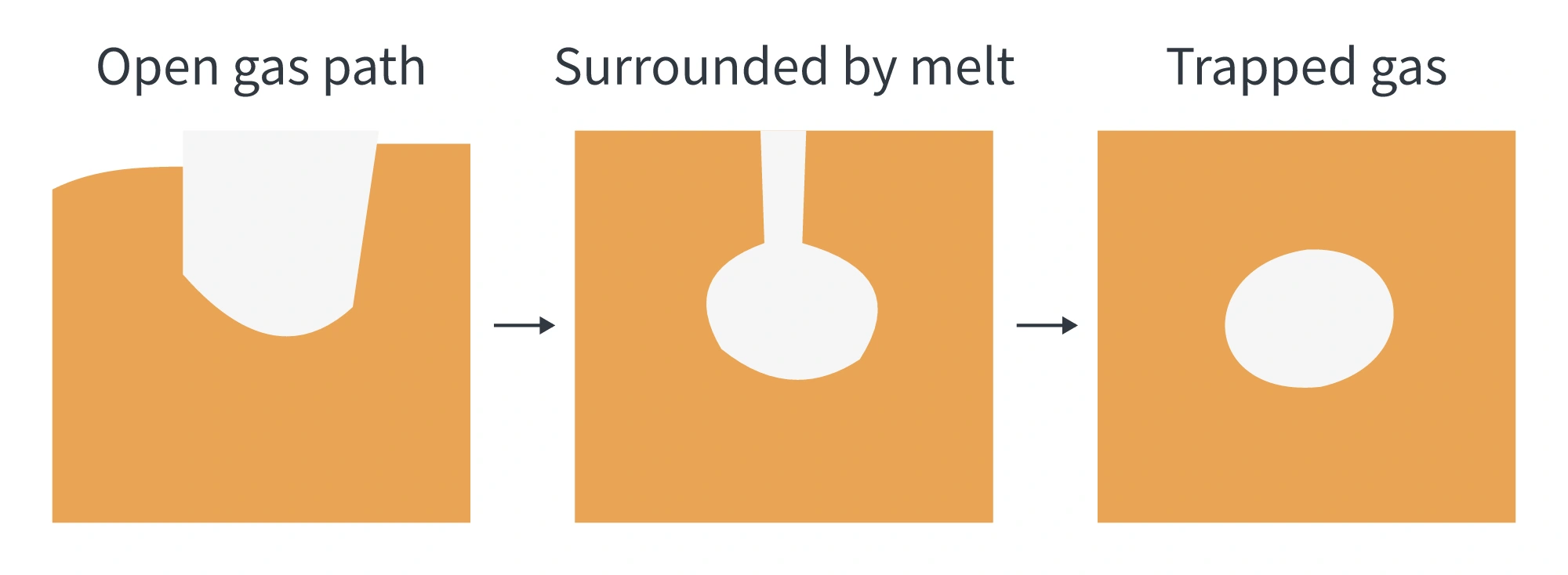
Before filling begins, the mold cavity contains air. As molten metal enters, that air needs to escape through the vents. If separated streams rejoin, or the flow rolls over and encloses gas, the connection between the gas and the vent outlet can be cut off. As the metal solidifies, the space occupied by that gas remains as a gas pore.
The key question goes beyond whether a vent exists: can the gas reach the vent outlet before it is enclosed? Gas already surrounded by molten metal will not automatically escape through an additional vent opened elsewhere. Investigating air entrapment therefore means checking the flow direction from the ingate (the entrance through which molten metal enters the cavity), stream junctions, the last regions to fill, and their connections to vents and overflows.
Gas porosity also has other sources, such as dissolved gas coming out of solution during solidification. A rounded pore can suggest that gas contributed to its formation, but it does not establish inadequate mold venting as the cause.
Shrinkage Porosity: Feeding Cannot Keep Up with Contraction
Aluminum alloys contract as they solidify. If surrounding metal is still liquid and the connecting passage remains open, molten metal can feed the contracting region. This is shrinkage feeding.
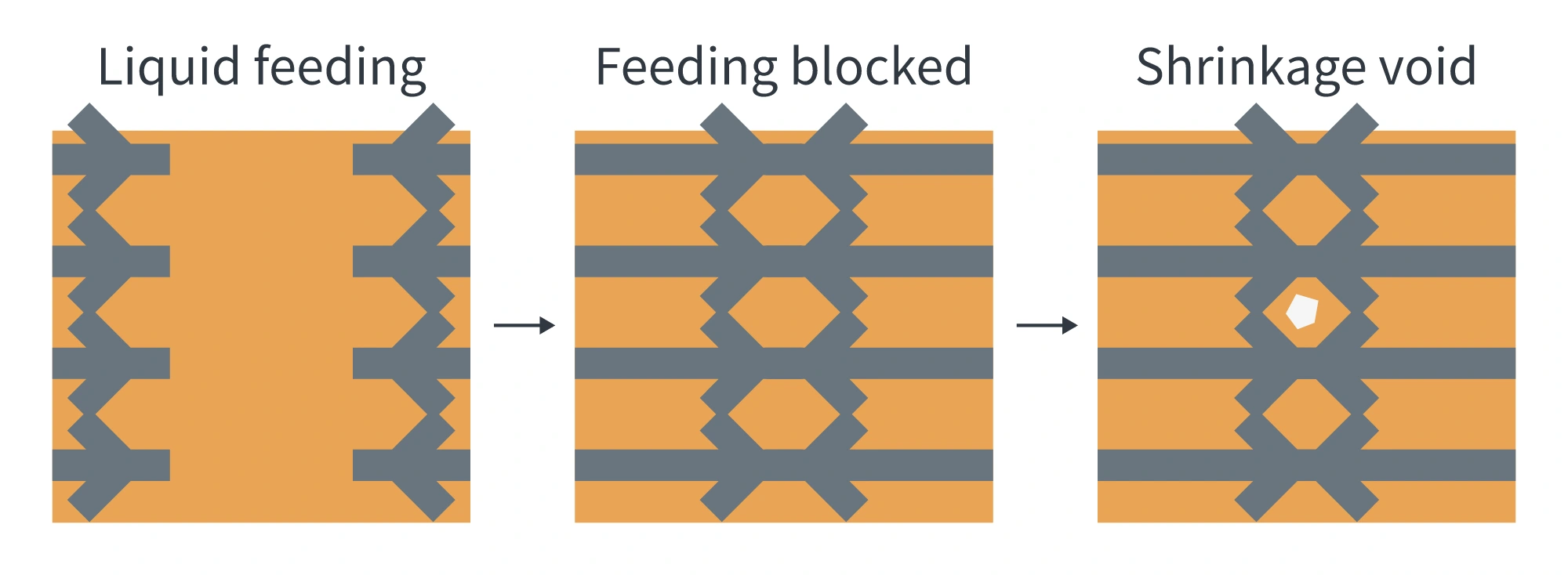
The problem arises when the region that needs feeding becomes isolated. Surrounding metal or a connecting passage solidifies first; the isolated liquid continues to solidify and contract, but feed metal can no longer reach it. The resulting voids become shrinkage cavities or distributed shrinkage porosity. Thicker regions are more likely to solidify last, but wall thickness is only a clue: the actual solidification sequence also depends on heat removal through the mold and the cooling layout.
A hot spot is a local region that solidifies later than its surroundings. Checking hot spots identifies where feeding is needed; checking the ingate and related passages establishes whether feed metal can still reach those regions.
Intensification means increasing the pressure applied to the molten metal to help it feed a contracting region. Setting intensification on the machine does not guarantee continued effective feeding there. Once the ingate or feeding passage has solidified, liquid metal can no longer feed through that passage.
In the three stages below, follow the central orange liquid region and check whether it still connects to other liquid metal. As the gray solid regions join, the remaining orange liquid is divided into isolated pockets that feed metal can no longer reach.
What Can Real Pores Tell You at the First Inspection?
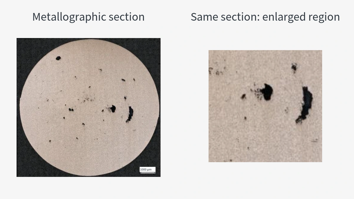
The opening metallographic image shows an A356 aluminum alloy specimen produced by high-pressure die casting. The black pores have different shapes, but this overall section alone cannot establish the cause of every pore.
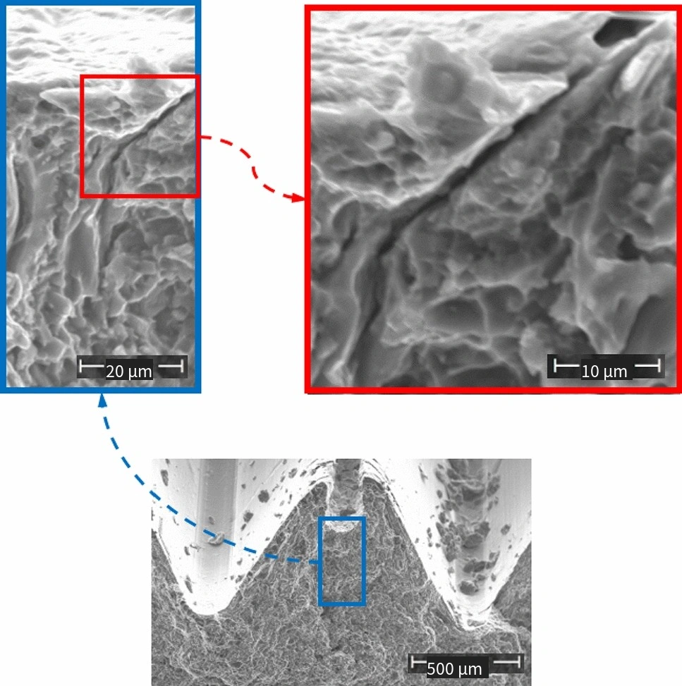
The optical micrographs below show an AlSi9Cu3(Fe) aluminum die-cast compressor component that has undergone impregnation sealing. Compare the more rounded pores near the top of the left image with the irregular pore edges in its middle and lower regions: gas and shrinkage porosity coexist on the same section. The right image shows a detail of microporosity. The two images have different magnifications.
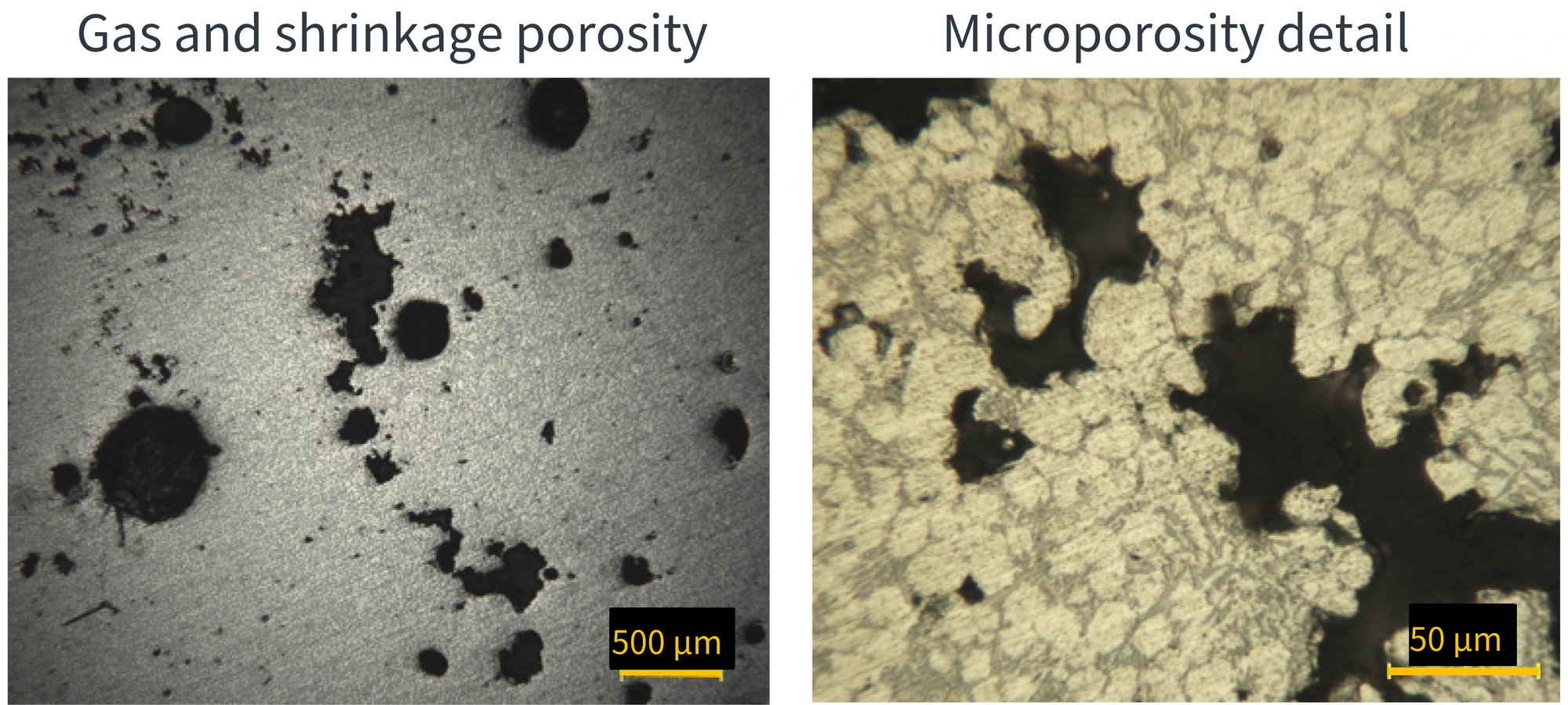
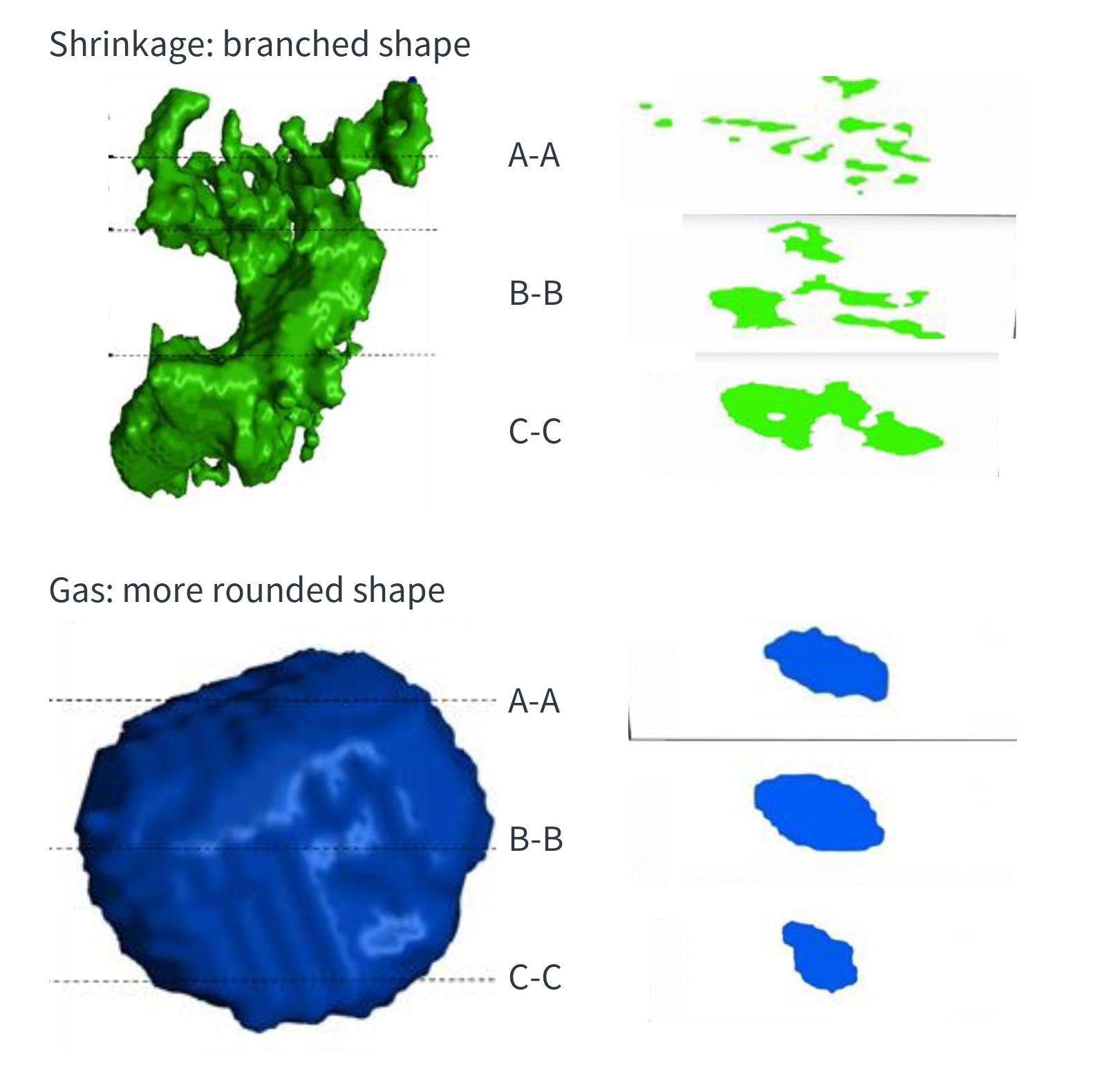
First examine the pore edges on the actual section. Then use the examples of three-dimensional pore shapes and sections below to understand why the same internal pore can look different on different cutting planes.
On a prepared and polished metallographic section, the pore edges are particularly useful. Typical gas pores have smoother outlines and often approach a spherical shape in three dimensions. Typical shrinkage pores are irregular and extend through spaces between dendrites. Dendrites are branching, tree-like crystals that grow during solidification; the spaces between them can give shrinkage pores a branched shape.
| What to Examine | Typical Clues to Gas Involvement | Typical Clues to Solidification Shrinkage |
|---|---|---|
| Pore edges on a polished section | Smoother outlines, often circular or elliptical | Irregular outlines, possibly branched or distributed voids |
| Three-dimensional pore shape | Often closer to spherical | May have branches, necks, and complex connections |
| Related process questions | How did gas enter, where was it enclosed, and could it escape? | Which region solidified last, and when did it lose its feeding passage? |
| Checks in the mold | Filling pattern, stream junctions, and connections to vents and overflows | Hot spots, cooling layout, and freezing of the ingate and feeding passages |
The shapes in this table are clues for an initial assessment. Metallographic research supports differences between typical gas and shrinkage pores, but a round pore does not prove air entrapment, and a branched pore cannot identify a faulty cooling channel by itself. Moving from pore shape to a mold-related root cause still requires evidence about location and process.
A plane cutting through a branched three-dimensional pore may expose only part of it. A section photograph may therefore miss the full shape, and the opening on a machined surface is not necessarily the pore’s largest internal dimension. A small opening in a photograph does not mean the entire internal pore is that small.
Map the Pore Location Back to the Mold
Start by marking the exposed pore on the casting drawing. Record which machining operation exposed it, how much machining allowance was removed, and whether it lies in a thick wall, at a rib root, in a boss, or in a thin wall. Then relate that same location to the gating system, vent and overflow layout, cooling layout, and available filling and solidification analyses.
The most useful comparisons are whether the pore region corresponds to a gas-trapping region, and whether it corresponds to a region that solidifies last. Simulation can suggest locations to investigate; inspection of the current casting tests those predictions. An air-entrapment plot from a simulation is not a photograph of measured gas porosity.
Suspected Air Entrapment: Follow the Gas Escape Route
First examine how molten metal reaches the pore region. If two streams meet there, check where the air can go before they join. If the region fills last, check whether it still has an open connection to the vent outlet.
Vents carry gas out. Overflow pockets receive some molten metal outside the cavity and can work together with the vents. Their effectiveness depends on their position and connections. Counting pockets or measuring their volume alone cannot show whether they connect to the gas and advancing metal front that need to leave the cavity.
Use the actual layout to check three questions:
- Where do the outlets connect? Compare vent and overflow entrances with the last regions to fill and the stream junctions, and establish whether a gas escape route exists.
- Do the passages remain effective? Inspect the actual vents, overflow entrances, and outlets for blockages or changes to the designed connections. If a vacuum system is used, also check its actual connections and operating condition.
- Does filling match the design conditions? Compare mold-trial records with simulation inputs, checking the shot process and filling sequence. Changing vent geometry alone cannot replace checking where air entrapment occurs.
These are investigation questions, not instructions to enlarge a vent whenever a pore appears. Vent dimensions, overflow dimensions, and shot parameters must suit the current alloy, casting, and equipment. This article gives no universal settings.
Suspected Shrinkage: Follow the Feeding Route
Compare the pore region with the solidification analysis to see whether it lies in a region that solidifies last. If pores occur at a transition between thick and thin sections, check whether local cooling changes the solidification sequence. The observation that a region is thick is not enough to complete the diagnosis.
Next, trace the feeding route. Is there a narrow section between the ingate and the pore region that solidifies first? Is that passage still open when feeding is needed? Does the timing of intensification match the timing of passage freezing?
This sequence explains why enlarging vents may not eliminate shrinkage porosity. Venting improves gas escape; shrinkage porosity requires feeding during solidification contraction. If both gas entrapment and shrinkage contribute to pore formation, both sets of relationships need checking in the same region.
What Evidence Do Photos, X-Rays, and CT Add?
Ordinary photographs record the location and opening of an exposed pore. Metallography on a polished section shows the pore edges and their relationship to the surrounding microstructure. Both provide information about a surface or a section.
An X-ray image is a projection along the beam direction. It helps examine the internal distribution of pores, but pores at different depths may overlap in the same image. CT (computed tomography) uses three-dimensional reconstruction to help reveal pore shapes, locations, and connections inside the actual part. For both methods, the smallest detectable pore depends on the actual inspection resolution.
If only a photograph of a machined surface is available, first preserve the location and machining-depth information rather than rushing to classify the pore. When internal morphology needs confirmation, arrange suitable inspection and relate the three-dimensional pore or metallographic section to the same casting region.
This investigation should produce a judgment that can be tested: which evidence points to gas involvement, which points to solidification shrinkage, and where the corresponding vents, overflows, or hot spots lie in the mold. After a change, compare the same pore region under the same inspection conditions to establish whether the change addressed the actual problem.