Mold acceptance is not a box-checking exercise where someone takes a photo after the T0 trial and walks away. The moment purchasing signs off, the hard metrics for dimensions, appearance, and assembly become the only solid basis for negotiating rework or reimbursement with the mold supplier. If those metrics are not quantified in the contract, the supplier can hide behind vague claims that the mold is “basically acceptable.”
This checklist follows the T0/T1/T2 trial stages. Dimensions are judged by tolerance class and Cpk, appearance by Class A/B/C surfaces and defect limits, and assembly by gap, flushness, and GD&T. The trial report must also be checked for locked process parameters and common ways Cpk data gets manipulated. Purchasing can match the report against this list directly, without relying on verbal explanations from the mold supplier.
moldsteells is an Injection Mold manufacturer serving automotive interior and exterior trim parts. Our standard accuracy is ±0.005-0.01 mm. Critical dimensions are controlled to Cpk 1.33 or higher, and a coordinate measuring machine (CMM) provides a full-dimensional inspection report. The checklist below is the same internal acceptance standard we provide to purchasing teams.
T0/T1/T2 Framework
T0 is the first trial shot, or FOT (First Off Tool). Its purpose is to verify whether the mold structure can run at all—whether the mold cavity fills completely, whether sliders and lifters move smoothly, and whether there is severe flash or short shot. T0 samples will always contain defects. Sink marks, warpage, and out-of-spec dimensions are normal at this stage. T0 samples cannot be used for functional testing, and they must never be treated as customer approval samples. Passing off T0 parts as T1 parts is one of the worst tricks in the business. Once purchasing signs, every downstream problem becomes the buyer’s problem.
T1 is the first formal trial after mold correction. At this stage, dimensions, appearance, and assembly are reviewed against customer requirements. A full-dimensional inspection report is required. The coordinate measuring machine (CMM) must check the complete dimension set, item by item, against drawing GD&T requirements. Starting from T1, process parameters must be locked: melt temperature, mold temperature, injection speed, holding pressure, holding time, cooling time, and cycle time. All seven items must appear in the trial report. Any drift in production counts as an unapproved change.
T2 verifies stability at production cycle time. The mold must run continuously for 200-500 shots, or 300-1000 shots for precision automotive parts, to calculate Cpk and confirm process capability. Final acceptance is not based on one good part. It depends on whether the dimensional distribution stays stable during continuous production.
Hard Dimensional Metrics
Start with CC and SC Dimensions
Not every dimension needs to be held to ±0.01 mm. That would drive costs through the roof. The automotive industry classifies dimensions under APQP: CC (Critical Characteristic) dimensions relate to safety and regulations, SC (Significant Characteristic) dimensions relate to function and assembly, and the rest follow general tolerances. Critical dimensions usually account for 20%-30% of all dimensions on a part, based on industry practice. Before acceptance, purchasing should require the mold supplier to mark the CC/SC list on the drawing. That list is the foundation of acceptance and a key negotiation tool.
Tolerance Standards Comparison
The tolerance standard must be defined before acceptance. China currently uses GB/T 14486-2008, Dimensional Tolerances for Plastic Molded Parts, with seven classes from MT1 to MT7. MT1 and MT2 are precision grades, MT3 to MT5 are standard grades, and MT6 and MT7 are free-dimension grades. German programs use DIN 16742, which replaced the older DIN 16901 and divides tolerances into six groups from 110 to 160 based on material and size. International programs use ISO 20457:2018, with nine tolerance grades from TG1 to TG9. China’s automotive standard QC/T 29017-1991 is more specific to automotive parts than GB/T 14486. The priority order is OEM corporate standard > QC/T 29017 > GB/T 14486 > ISO 20457/DIN 16742. This must be confirmed before the contract is signed.
| Standard No. | System | Grade | Typical Application |
|---|---|---|---|
| GB/T 14486-2008 | Chinese national standard | MT1-MT7 | Default for general plastic parts |
| QC/T 29017-1991 | Chinese automotive industry standard | Unspecified tolerances | Priority for automotive interior and exterior trim |
| ISO 20457:2018 | International | TG1-TG9 (W/NW split) | Export parts and multi-standard projects |
| DIN 16742 | German | Six groups, 110-160 | German OEM programs |
The key point in ISO 20457 is the distinction between W and NW. W refers to mold-related dimensions, Type B, which are not affected by mold closing or slider action. NW refers to non-mold-related dimensions, Type A, which are affected by mold closing, sliders, or ejector variation. NW tolerances are larger than W tolerances. That makes ISO 20457 more rigorous than the old DIN system. Purchasing cannot apply a single blanket tolerance to both.
Shrinkage and Cavity Compensation
Plastic shrinks during cooling, so the mold cavity must be oversized in advance to compensate. Typical shrinkage ranges for common automotive interior and exterior materials are PP+EPDM-T20 for bumper skins, 0.9%-1.3%; PA6-GF30 for structural parts, 0.3%-0.6%; and PC/ABS for instrument panel carriers, 0.5%-0.7%. Glass-filled materials show strong anisotropy, so shrinkage differs along and across the flow direction. As a rough rule, the mold cavity dimension is enlarged based on finished part size ÷ (1 — shrinkage rate). In practice, the real compensation level depends on moldmaker experience, not just a handbook value, and it still needs fine-tuning after the T0 trial.
Hard Appearance Metrics
Appearance is where purchasing is most likely to lose ground. If defect acceptance limits are not fixed in the contract, the mold supplier can always fall back on “normal industry practice.”
How to Define Class A/B/C Surfaces
Appearance acceptance starts with surface classification. Class A surfaces are the primary visible surfaces that users see directly in daily use, such as the front face of the instrument panel, the center console panel, and the outer surface of the bumper. Class B surfaces are secondary visible surfaces, seen indirectly when a door is opened or from a certain angle, such as instrument panel side faces, pillar trim, and the lower door panel area. Class C surfaces are hidden assembly surfaces, such as rear ribs, clip seats, and mounting brackets. The classification must be based on the final vehicle assembly condition, not the loose part. A surface that looks like Class A on the loose part may become Class B after vehicle assembly.
Acceptance Limits for 8 Common Defects
The table below shows acceptance limits for eight common defects across Class A/B/C surfaces. These are industry reference values. The final authority must be the customer-approved limit sample.
| Defect | Industry Term | Class A Surface | Class B Surface | Class C Surface |
|---|---|---|---|---|
| Sink marks | Sink marks | Depth ≤0.05 mm and not visible | ≤0.1 mm | ≤0.2 mm |
| Weld lines | Weld lines | Not allowed in textured or glossy visible areas | Allowed if height difference ≤ 0.05 mm | No limit |
| Flash | Flash | Zero tolerance, parting line overflow ≤0.05 mm | ≤0.1 mm | ≤0.3 mm |
| Ejector blush | Ejector pin marks | Not allowed | Slight marks allowed, no whitening | Must not affect function |
| Silver streaks | Flow marks / splay | Not allowed | Slight, ≤3 mm, max 2 spots | Must not affect function |
| Burn marks | Burn marks | Zero tolerance | Slight yellowing acceptable | Must not affect function |
| Orange peel | Orange peel | Gloss deviation ≤2 GU | ≤5 GU | No limit |
These are industry reference values. The final authority must be the customer-approved limit sample.
Purchasing should be careful not to treat “industry reference values” as absolute rules. Before acceptance, both parties must sign off on sealed limit samples, and every batch must be checked against them. Different OEMs emphasize different methods. Some rely on quantified data, such as VDI texture consistency. Some rely on signed visual samples. Some rely on SPC process capability. If a supplier serves multiple OEMs, the files must be managed separately. One sample set cannot be used across all programs.
SPI/VDI Surface Grades and Inspection Environment
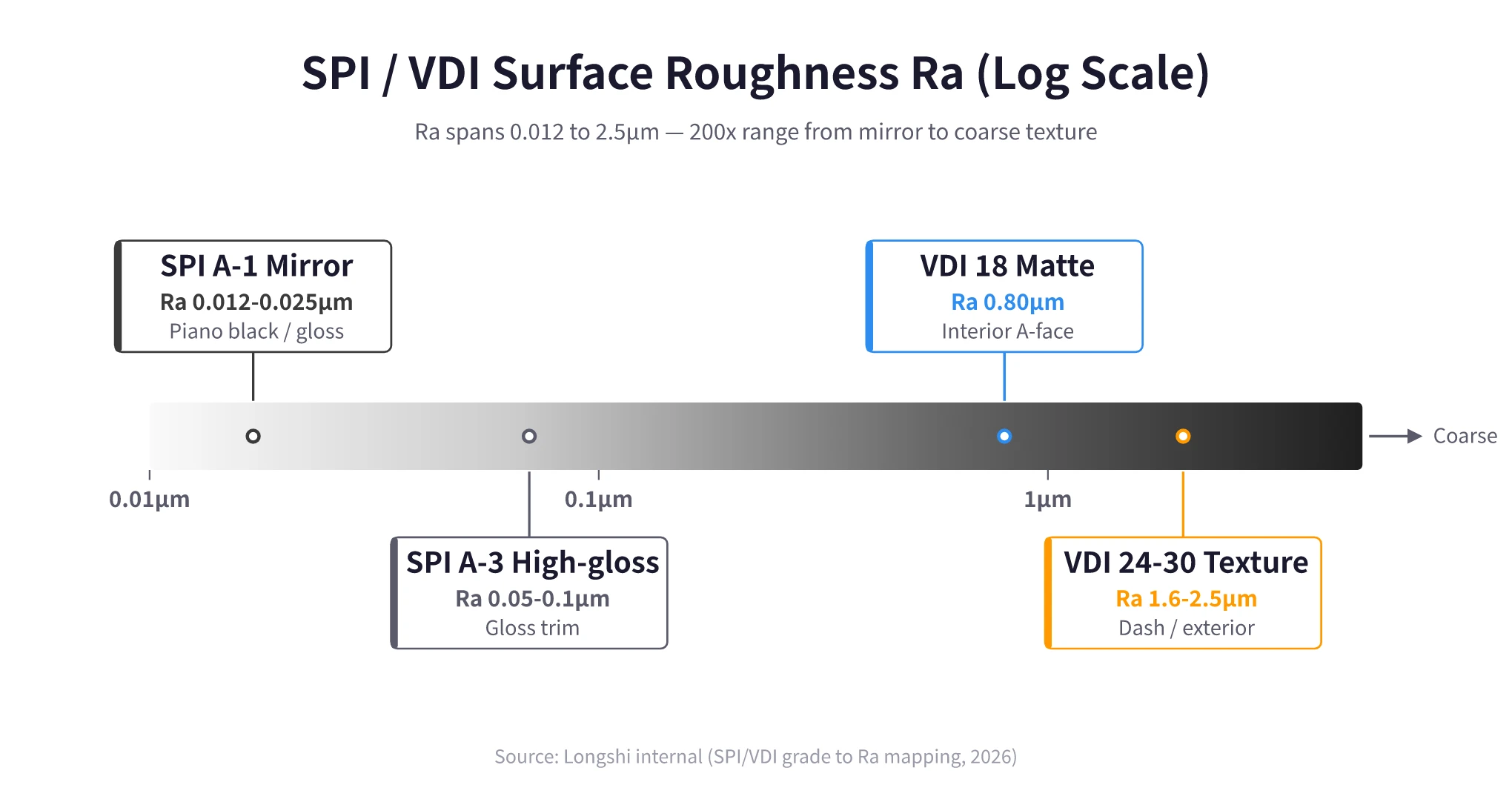
Visible surfaces must also be accepted against SPI or VDI surface grades. For a Mirror Finish Injection Mold, SPI polishing grades run from A1 to D3, with 12 levels in total. A-1 is a mirror finish at Ra 0.012-0.025 μm, finished with 6000-grit diamond paste. A-2 and A-3 are high-gloss surfaces. The B series covers paper-polished finishes, the C series stone finishes, and the D series blasted textures. VDI 3400 is the German texture standard for etched surfaces. VDI 18, Ra 0.80 μm, is commonly used on Class A interior surfaces. VDI 21-24, Ra 1.12-1.60 μm, is common for instrument panels and bumper skins. Above VDI 30 is a coarse texture for exterior trim. Ra is the arithmetic average roughness profile deviation. The lower the Ra, the smoother the surface.
The inspection environment must also be fixed in writing: D65 standard light source at 800-1200 lux, viewing angle 45° ±15°, viewing distance 30 ±5 cm, neutral gray background at Munsell N5, and no more than 10 seconds of observation per part. Hot parts fresh off the line cannot be judged directly. If these conditions are not written into the contract, appearance acceptance turns into a matter of opinion.
Hard Assembly Metrics
A compliant loose part does not guarantee compliant vehicle assembly. Hard assembly metrics focus on gap, flushness, and GD&T.
Gap and Flushness
Gap is the distance between two mating surfaces. Flushness is the height difference between those surfaces. Typical values for automotive interior and exterior trim, based on SAE J1100 and OEM DTS dimensional specifications, are shown below. Final judgment must follow the customer DTS specification.
| Assembly Location | Gap | Flushness |
|---|---|---|
| Bumper to fender | 3.0 ±0.5 mm | 0 ±0.5 mm |
| Instrument panel to door trim | 1.0 ±0.3 mm | 0 ±0.5 mm |
| Front to rear door match | 4.0 ± 1.0 mm | 0 ±1.0 mm |
| Lamp to body | 2.0 ±0.5 mm | 0 ±0.5 mm |
| Grille to hood | 3.5 ±0.5 mm | — |
These are typical reference values. Final judgment must follow the customer DTS dimensional specification.
Flushness at the parting line is a red line in acceptance. In Class A visible zones, flash must be ≤0.02 mm and flushness must be ≤0.03 mm, with zero tolerance for any visible defect. Many OEMs reject parts outright when parting line flushness exceeds 0.05 mm.
GD&T Requirements
For plastic part GD&T, based on ISO 1101 and GB/T 1182 and grouped by part size, typical flatness limits are 0.1-0.3 mm for small parts under 200 mm, 0.3-0.5 mm for medium parts from 200-500 mm, and 0.5-1.0 mm for large parts above 500 mm. Typical position tolerance values are φ0.2-0.5 for small parts, φ0.5-1.0 for medium parts, and φ1.0-2.0 for large parts. Plastic part GD&T is usually one order of magnitude looser than for metal parts. Metal-part standards cannot be applied directly to plastic parts. When reviewing assembly drawings, purchasing should always check the GD&T feature control frames, especially MMC modifiers.
Snap-Fit Engagement
Snap-fit engagement depends on elastic deformation of plastic. The design must control two angles: the insertion angle for assembly guidance must be smaller than the retention angle for pull-off resistance, and the interference level depends on material type. The snap root thickness should be 50%-60% of nominal wall thickness to avoid stress concentration. Deflection should be controlled to 1.5%-2.5% of wall thickness. The mold supplier should already have verified these values during design. At acceptance, a pull-off force test on several clips is enough to confirm whether the design works.
Critical Data in the Trial Report
The trial report is the core evidence in mold acceptance. Purchasing should never read only the conclusion. The raw data matters.
Seven locked process parameters that must be checked (locked from T1 onward; any production drift counts as an unapproved change):
| Parameter | What It Locks | Manipulation Risk |
|---|---|---|
| Melt temperature | Controls flowability and appearance | Raised to hide sink marks, but parts become brittle |
| Mold temperature | Controls crystallization and warpage | Lowered to raise output, but warpage increases |
| Injection speed | Controls filling and appearance | Raised to hide short shot, causing burn marks and flow marks / splay |
| Holding pressure | Controls sink and dimensions | Raised to pack out shrinkage, making parts oversized |
| Holding time | Controls dimensional stability | Shortened to save time, leading to later shrinkage |
| Cooling time | Controls demolding deformation | Shortened to save time, causing ejector blush and deformation |
| Cycle time | Controls cost and stability | Shortened to cut costs, causing drift in all key metrics |
How to read a Cpk report:
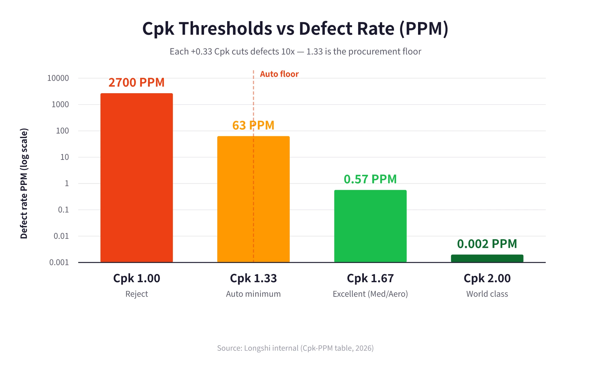
The Cpk thresholds are straightforward. Cpk <1.0 is unacceptable, with a defect rate above 2700 PPM. Cpk 1.0-1.33 is borderline and needs improvement. Cpk ≥ 1.33 is acceptable, with a defect rate of 63 PPM or less, and it is the minimum threshold in automotive. Cpk ≥ 1.67 is excellent and typical of medical or aerospace work. Cpk ≥ 2.0 is world-class. For non-critical dimensions, Cpk 1.0 may be acceptable, but only if that is written into the control plan.
Purchasing cannot give ground on the Cpk 1.33 line.
There are four common ways Cpk reports get manipulated. First is sample selection bias, where the supplier picks only parts close to nominal. Counter this with stratified random sampling by cavity number. Second is measurement system manipulation, such as using a worn probe to hide under-compensation of shrinkage. Counter this by checking the coordinate measuring machine (CMM) on site with a standard sphere and requiring MSA GR&R <10%. Third is using Ppk instead of Cpk because the number looks better. Counter this by specifying Cpk explicitly and fixing subgroup size at n=5. Fourth is tolerance substitution, where the supplier calculates Cpk against drawing tolerance instead of functional tolerance. Counter this by requiring a GD&T functional gage plan.
Do not mix up the three major production approval systems: PPAP, ISIR, and FAI. PPAP is the Production Part Approval Process under the AIAG North American system, commonly submitted at Level 3. ISIR is the Initial Sample Inspection Report under the German VDA system. FAI is First Article Inspection under AS9102 for aerospace and general manufacturing. All three serve a similar purpose—to verify before mass production that the supplier can consistently meet drawing requirements—but they come from different systems. The contract should specify the one required by the OEM. Automotive Tier 1 suppliers must also pass the VDA 6.3 process audit, using elements P2-P7 in the current 2023 edition, alongside IATF 16949.
What to Do if Acceptance Fails
If acceptance fails, the outcome usually falls into one of three categories: minor rework, major rework, or scrap. The decision depends on how the problems are distributed and what technical repair route is available.
Four mold correction methods, listed from small to large intervention:
- Weld repair (laser welding or TIG welding to add steel)—suitable for local wear, small missing areas, and textured surface repair. The downside is heat-affected zone (HAZ) deformation and weld color difference. Pre-hardened steel can soften after local annealing, so this method must be used carefully.
- Insert replacement — suitable for local structural changes, wear-prone areas, and venting correction. The insert fit tolerance is H₇/m6. The advantage is that the main mold base stays untouched.
- Slider adjustment — suitable for undercut location changes, insufficient core-pull stroke, and wear repair. This is a larger change and may require another mold base strength review.
- Runner modification — suitable for fill imbalance and poor weld-line location. Changes are relatively smaller in cold runner molds and much more costly in hot runner molds.
Responsibility allocation under standard industry practice: if the mold supplier did not machine to the approved drawing, failed to meet steel hardness or material requirements, or missed the agreed tool life, typically 300,000 shots, the mold supplier bears 100% responsibility. If the product designer changed the structure, such as wall thickness, undercut, or draft angle, then the product design side bears 100%. If the molder damaged the mold through improper processing, such as crushing the parting line with excessive clamp force, then the molding plant bears responsibility. Mixed responsibility is common, often split from 30:70 to 50:50 through negotiation.
Preventive contract clauses are where purchasing should spend its real effort:
- Lock the trial material, including grade, supplier, and drying conditions. The mold supplier must not be allowed to switch materials temporarily to hide problems.
- Quantify the acceptance standard, including critical dimension Cpk ≥1.33, appearance limit sample number, lighting angle, and tool life in number of shots.
- Set response time for mold correction, such as requiring a corrective plan within X working days after T0 failure.
- Set a cost ceiling, such as triggering a formal responsibility review when one round of mold modification exceeds X% the total mold price.
If the contract is vague, purchasing pays the bill when production problems show up.
Mold acceptance ultimately comes down to measurable criteria, not the mold supplier’s promises. If Cpk is below 1.33, the tool must be reworked. If appearance defects exceed the approved limit sample, compensation, or rework must be negotiated. If non-appearance assembly flushness exceeds 0.1 mm, PPAP sign-off should be held back. When the trial report, limit samples, and contract clauses all line up, purchasing can sign with confidence.
If it is still unclear which dimensions should be controlled as CC characteristics or which appearance defect limits should be written into the contract, send over the drawing and the limit sample requirements. As an Injection Mold Manufacturer, moldsteells can prepare a comparison checklist to help review the trial report and control the PPAP sign-off point.