During trials of a multi-cavity mold, a sample with flash on one side and a sample with a missing corner on the other create conflicting demands on the process: the short-shot cavity still needs more melt, while melt has already escaped beyond the cavity that flashes. Watching a single pressure value on the machine makes it difficult to know which side to address.
To identify the cause, first examine how each mold cavity fills. Does the difference appear at the gate entrance, or only after the melt enters the cavity? Is the flash associated with earlier filling, or is there a separate local gap? These observations determine whether to investigate the runners, the cavities, or the transition from filling to packing.
Why Flash and Short Shots Can Occur in the Same Mold
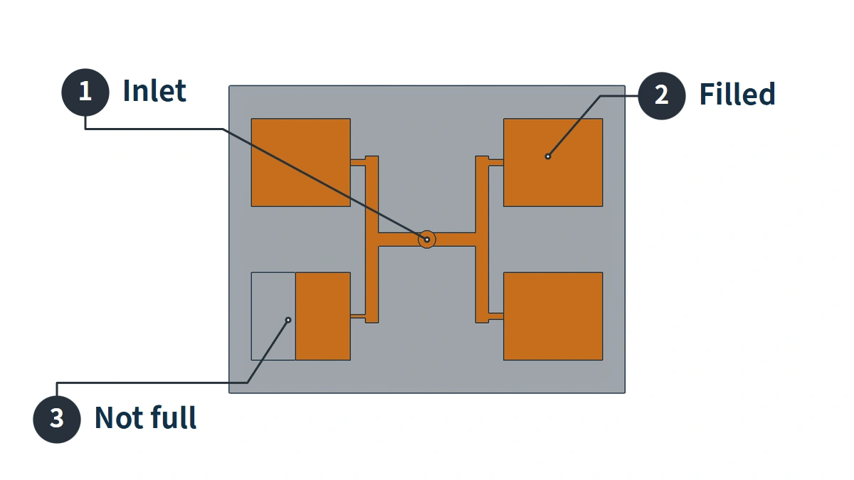
During an injection shot, melt enters the main runner through a common inlet, travels along branch runners, and passes through their respective gates into multiple cavities. The machine controls this shared injection shot. How much melt each branch actually receives also depends on flow resistance and the condition of the gates and cavities.
Suppose two cavities of the same shape have different feed passages: one gate is unobstructed, while the other has a restricted cross-section. At the same moment, the flow front in the first cavity can travel farther, while the second still has an unfilled region. Once the first cavity is full, it continues to experience pressure as long as its gate can transmit pressure and the machine continues injecting. Meanwhile, the second cavity may still be filling.
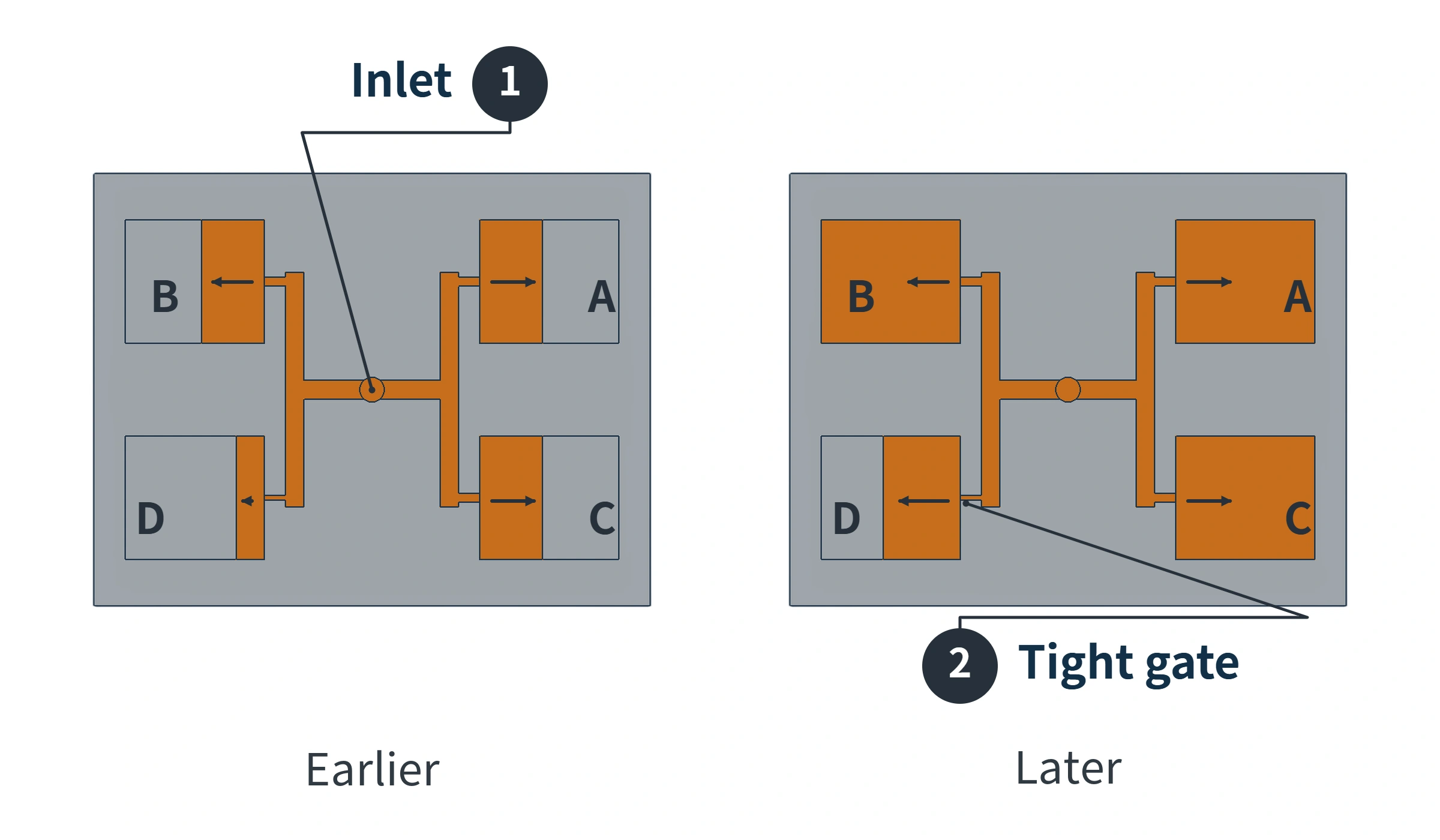
The illustration shows a difference in filling sequence; it does not mean that the lagging cavity will always remain incomplete. The issue is that extending injection or adjusting subsequent melt feeding to keep it filling also affects the cavities that are already full. Covestro’s technical guidance on thermoplastic injection molding for medical applications explains that earlier-filling cavities are more prone to flash, while later-filling cavities may be underfilled. Conditions that help the later-filling cavities can also worsen problems in those that fill first.
Filling first does not necessarily mean a cavity will flash. Flash occurs when melt enters a mating gap that should be sealed, leaving a thin edge after demolding. The parting surface is the interface where the two mold halves meet when the mold closes. Local wear, trapped debris, or an inability to maintain contact under pressure can allow melt to escape here. Continued pressure on a cavity that has already filled increases the risk of flash at these locations.
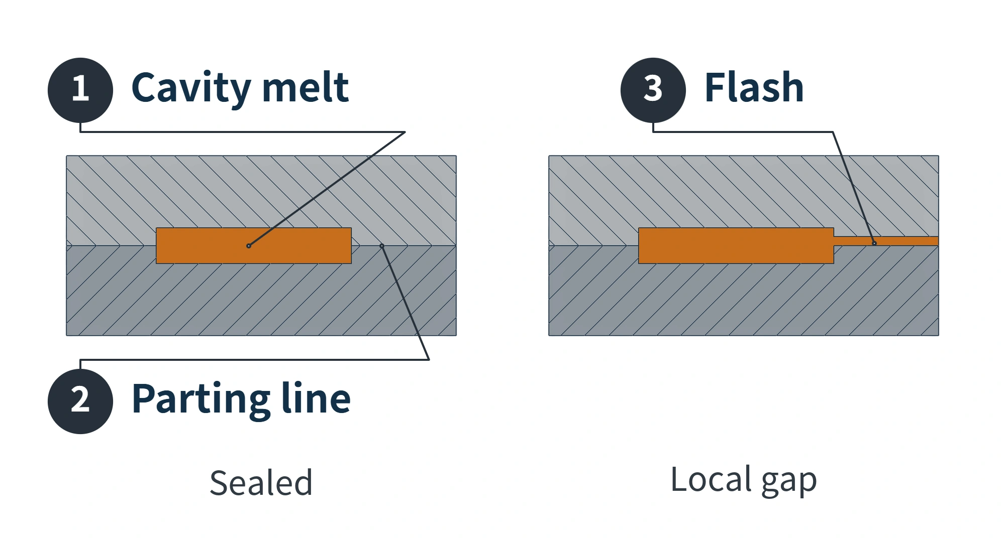
Opposite defects in the same mold can also result from two separate problems: wear at one cavity’s parting surface causes flash, while air trapped at the end of another cavity causes a short shot. This combination can occur even when runner distribution is reasonably balanced. The defects raise a question, but their appearance alone does not identify a single cause.
Check Each Cavity to Find Where Filling Starts to Differ
Here, examining individual cavity filling means analyzing how each cavity fills in turn. The mold still operates in its normal multi-cavity configuration. It does not mean blocking the other gates and trialing only one cavity.
After subsequent melt feeding, a complete sample may no longer reveal the initial differences between flow fronts. A short-shot study deliberately leaves parts incomplete so that their outlines show how far the melt traveled. Arranging samples at different fill levels by cavity number reveals the sequence that would otherwise remain hidden inside the mold.
For this comparison, first confirm that the material and machine operation are repeatable. Then keep injection velocity, material condition, and zone settings consistent while changing the position at which the filling stage ends to produce samples at different fill levels. A process engineer needs to confirm how to exclude second-stage melt feeding. Also check whether the screw continues forward beyond the set switchover position and pushes extra melt into the mold; this overshoot changes the outlines left by the short-shot samples. Setting holding time to zero and setting holding pressure to zero do not produce the same results on every machine, so neither should be treated as a universal test instruction.
Focus on two areas.
First, examine the entrance to each cavity. If early short-shot samples show that melt has entered several cavities supplied by one branch, but has not yet entered those on another, the difference has already developed before cavity entry. Follow the lagging cavities’ shared feed path and check the runner branches, hot-runner nozzles, or gate opening conditions. Do not immediately classify every late-filling cavity as an internal venting problem.
Then examine where the melt stops after entering. If melt has entered every cavity, but one flow front repeatedly stops at the same thin wall, narrow passage, or end region, check local resistance and venting there. As the melt advances, air inside the cavity needs an outlet. If that outlet is restricted, air becomes trapped in the last region to fill and impedes further melt entry. Changing only the upstream runners may not eliminate this local unfilled area.
One set of samples is insufficient to judge the cause. Check whether the filling sequence repeats, and whether the difference develops before cavity entry, grows gradually inside a cavity, or appears only at the last region to fill. Cavities lagging as a group suggest that their shared branch deserves inspection; a flow front stopping at a fixed location in one cavity suggests a local feature deserves inspection. Both can occur together.
Equal Runner Lengths Do Not Guarantee the Same Melt Conditions
Equal distances from the inlet to each cavity establish only that the paths have equal lengths. Runner cross-sections, turns, and gate conditions also need checking. Even when these geometric conditions match, melt at different positions can experience different shear before being directed toward different cavities.
The illustration below follows part of the path on the right side of an eight-cavity H-shaped runner. Point 1 is the T-junction that splits flow upward and downward; point 2 is the downstream junction that splits flow again toward the inner and outer cavities. The left-right split at the central inlet occurs before these points. Points 1 and 2 mark only the locations observed along this section.
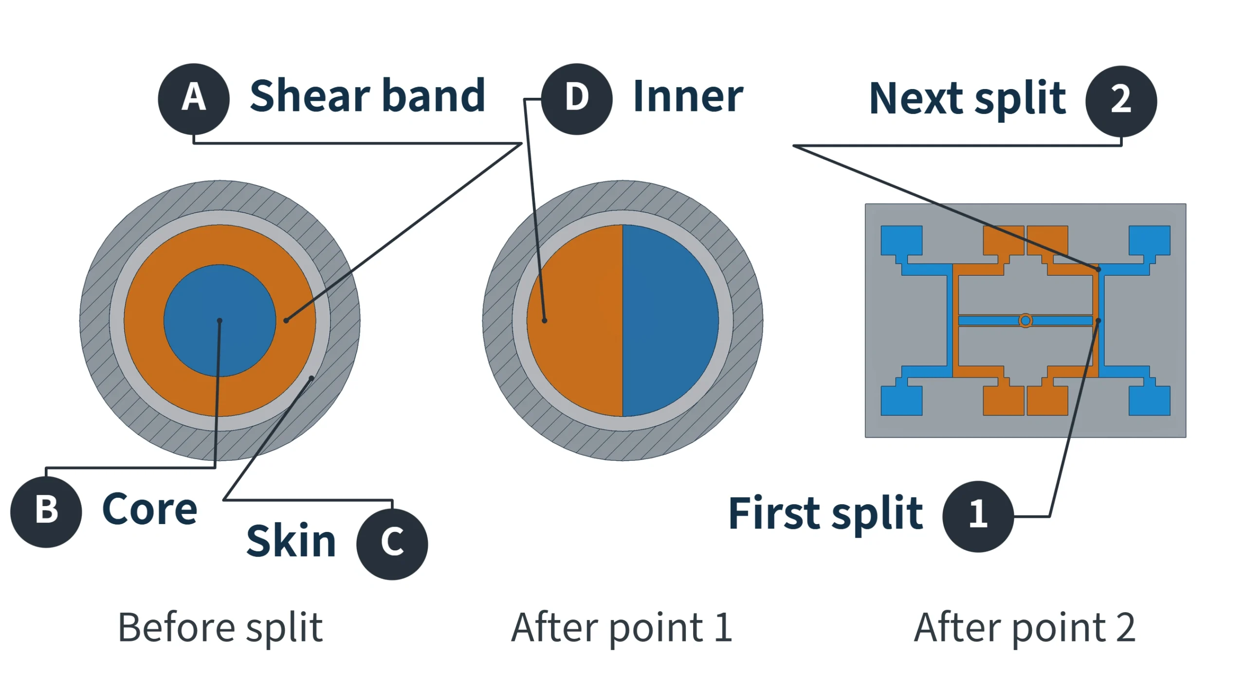
Melt layers inside the runner move at different velocities. Shear between layers generates heat, so the flowing shear band and the core can have different conditions. After point 1, the warmer shear band travels along the inside-corner side, while more of the core melt enters the other side. At point 2, the two sides are directed toward different downstream cavities.
With this layout and suitable material and process conditions, melt on the warmer side has lower viscosity, so the inner cavities may fill first. This comparison concerns relative conditions within the cross-section; the actual temperature difference must be established for the material and process. Equal runner lengths cannot replace filling evidence. Determining whether this imbalance occurs still requires cavity-by-cavity short-shot observations.
Understand Filling and Packing Before Increasing Pressure
In a conventional injection molding process that allows filling and packing to be controlled separately, the filling stage primarily controls the screw’s forward velocity, while the machine generates pressure to overcome flow resistance. The first-stage pressure limit is only the maximum pressure available. If actual pressure remains below that limit, raising it does not automatically apply extra pressure to every cavity. If pressure has already reached the limit, the set velocity may no longer be maintained.
The following example uses a mold with a conventional gate in which melt solidification stops feeding, to show when subsequent melt feeding takes place.
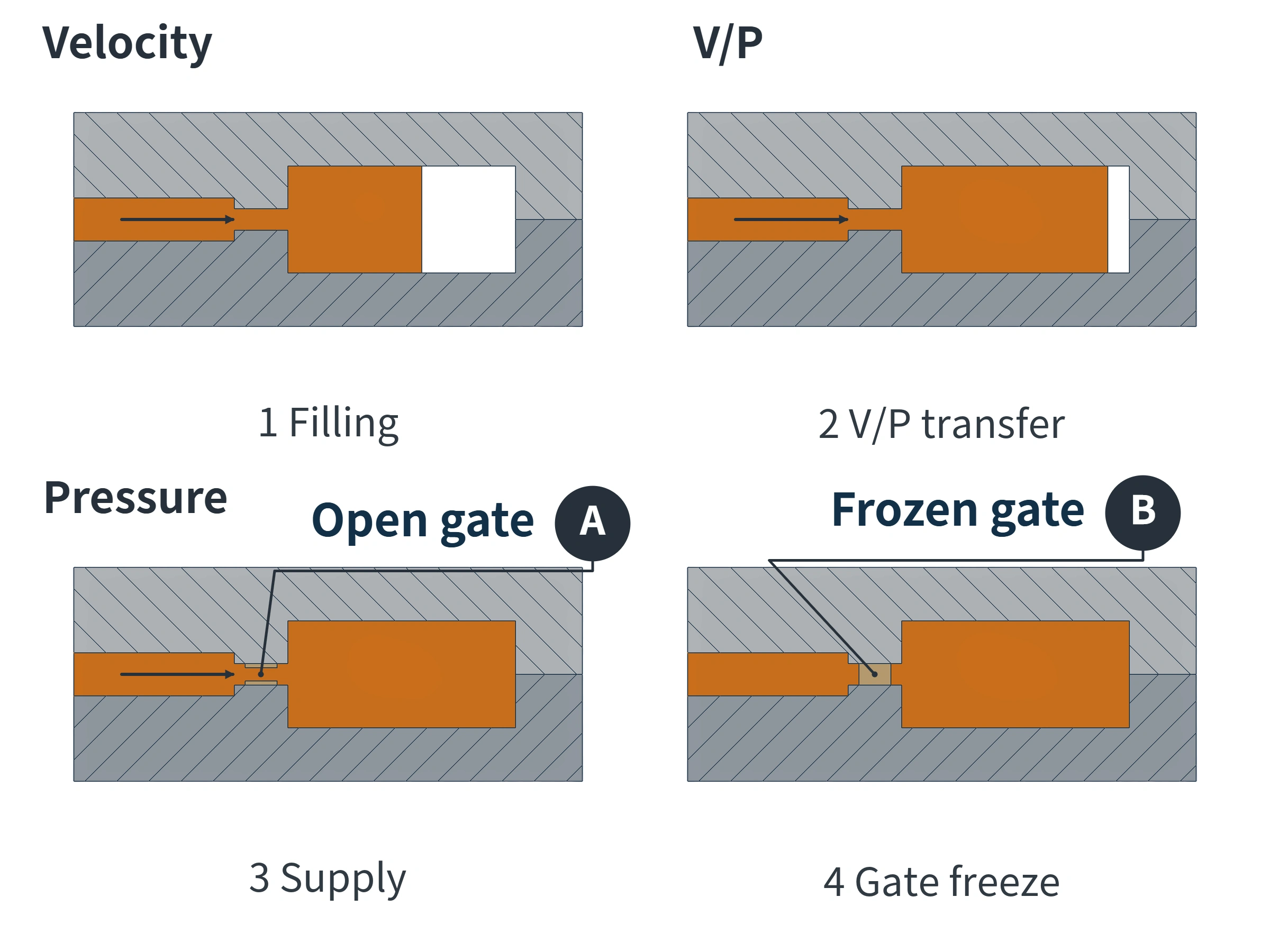
The transition from velocity control to pressure control is called V/P transfer. At this point, the cavities may be at different fill levels: cavities that filled first remain under pressure, while later-filling cavities still have unfilled regions. Subsequent melt feeding and holding pressure act on the cavities through gates that remain open. Increasing pressure or extending the duration may help the later-filling cavities, but can also increase overpacking in those that filled first.
When melt in a gate solidifies and seals the entire cross-section, the passage can no longer feed material. This is gate freeze-off. A valve-gated hot runner cuts off the inlet by mechanically closing a valve; valve closure and freeze-off are separate events. Restoring the machine’s forward velocity will not automatically correct a restricted gate or wear at the parting surface.
Finished-part weight shows the endpoint. The weight of short-shot parts produced without packing can help compare how much melt entered cavities of the same shape under the same conditions. Complete parts also reflect subsequent melt feeding. A 2025 four-cavity cold-runner study in Polymer Engineering & Science, conducted after filling balance had been confirmed, found that the same final weight could correspond to different cavity-pressure integrals: pressure integrated over time. Similar final weights therefore still need to be considered alongside the flow-front sequence and any available cavity-pressure records.
If fill levels also fluctuate from shot to shot under the same settings, first check material condition, metering, the check ring, and the actual switchover response to establish a stable comparison baseline. After addressing the issues, recheck each cavity’s flow front under the original short-shot conditions, then inspect complete samples for flash, missing sections, and weight. One acceptable finished part cannot replace a review of the process.
We are moldsteells, a Precision Mold Maker specializing in precision mold manufacturing. If you need to assess filling issues in a multi-cavity mold further, product drawings, trial-molded samples identified by cavity number, and process records can help us analyze the relationships between runners, gates, and cavities.