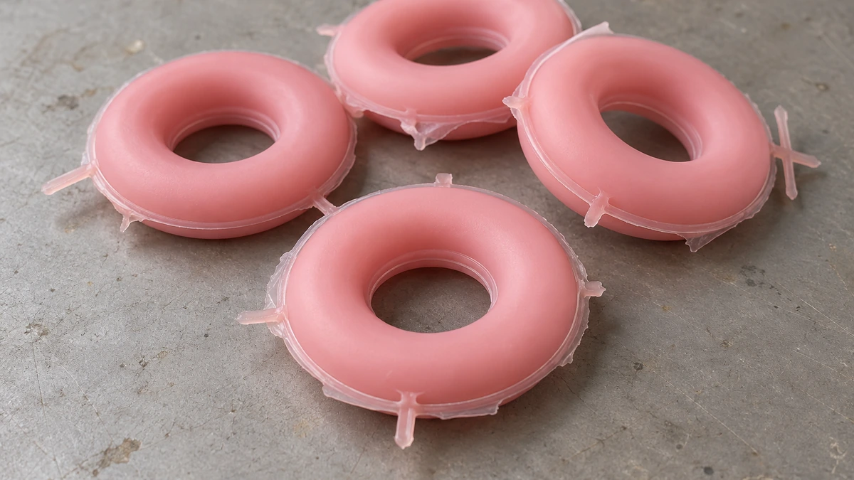
If the flash on a sample is thick or widespread, do not reduce the rubber charge immediately. Flash can also be related to charge placement, mold closure, compound flow, or cure behavior. When flash keeps returning at the same location, first check how the two mold halves mate instead of assuming that the parting surface is worn. Determine whether the flash enters the sealing contact band, then arrange the untrimmed samples by location, cavity number, and molding cycle. The pattern should help you judge whether the main suspect is inconsistent charge placement, excess material collecting in one area, or a local loss of mold contact. Once you have a leading suspect, change only one item per trial.
At moldsteells, when we design, machine, assemble, and run general trials for compression molds, we check parting-surface contact, overflow-groove condition, and critical sample dimensions together. To determine whether a seal is acceptable, the actual part must still be assembled by the agreed method and tested under its real operating conditions. Sample appearance alone is not enough.
When Does Flash Affect Sealing?
The parting line on a molded product is the line left where the two mold halves close against their parting surfaces. The thin rubber squeezed out along that line is called “flash.” In factories in Guangdong, it may also be called pi feng. These features appear next to one another, but they should not be treated as the same defect.
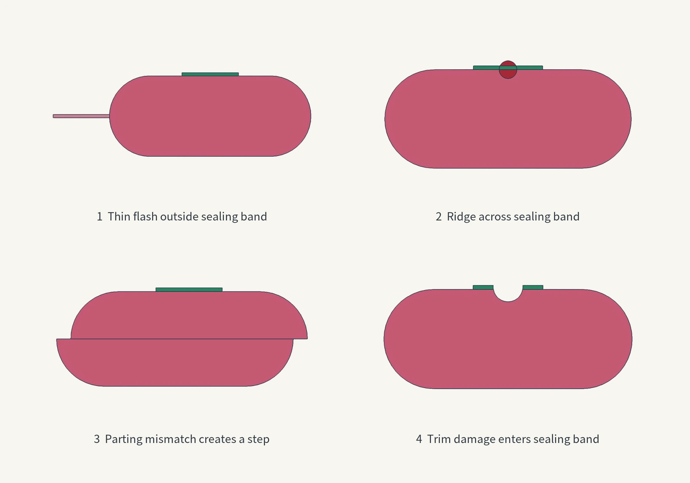
Start by marking the sealing contact band on both the drawing and the sample. This is the ring of surface that actually mates and carries the sealing load. A thin flash located entirely on a nonfunctional outer edge may mainly affect appearance and downstream trimming. A continuous parting-line projection, mold-half mismatch, notch, or rough-trimmed area that crosses the sealing contact band requires further functional investigation. Without the part cross-section, groove geometry, medium, pressure, and assembly condition, a photograph alone cannot prove that the visible flash will cause leakage.
Trimming also has limits. Scissors can remove a thin extension of rubber, but they cannot remove a parting-line projection, correct a mismatch between the mold halves, or restore a damaged functional edge. Cutting too deeply can also leave a notch in the sealing edge. A smooth-looking trimmed sample only shows that the excess film has been removed. It does not replace checks of the profile, critical dimensions, and sealing function.
Keep Untrimmed Samples Before Adjusting the Mold
Do not start the investigation by cutting or modifying the mold. After demolding, photograph the complete mold set, retain at least one group of untrimmed samples, and record the cavity number, molding cycle, compound batch, charge weight per cycle, preform shape, and charge placement. Note which side collects the overflow, along with any trapped rubber or damage on the parting surface.
If the first few cycles were not numbered, you do not need to wait for perfect records before starting. Arrange samples from the same batch together and check whether the condition affects every cavity or is concentrated in one cavity. Then see whether it repeats at a fixed location. If that is all the evidence currently supports, keep the conclusion at that level. From the next cycle onward, add cavity and cycle numbers, and use the same identifiers for weights and photographs.
An untrimmed sample preserves the original trace of where rubber crossed the closed interface and where excess material accumulated. If the samples are trimmed flat first and the team later relies on memory to discuss which side was thicker, it becomes difficult to tell whether a later improvement came from changing the charge, modifying a groove, or spotting the parting surface.
Do not photograph only the thickest short section. Begin with an overall image that shows the cavity number and the full parting line, then add close-ups at fixed locations. Keep lighting, angle, and scale as consistent as possible within each set. The records do not need to become a large quality-documentation system. They only need to reconnect each observation to the cycle, cavity, charge weight, charge placement, and flash location so that the next trial has a sound basis.
How to Read Location, Cavity, and Cycle Patterns
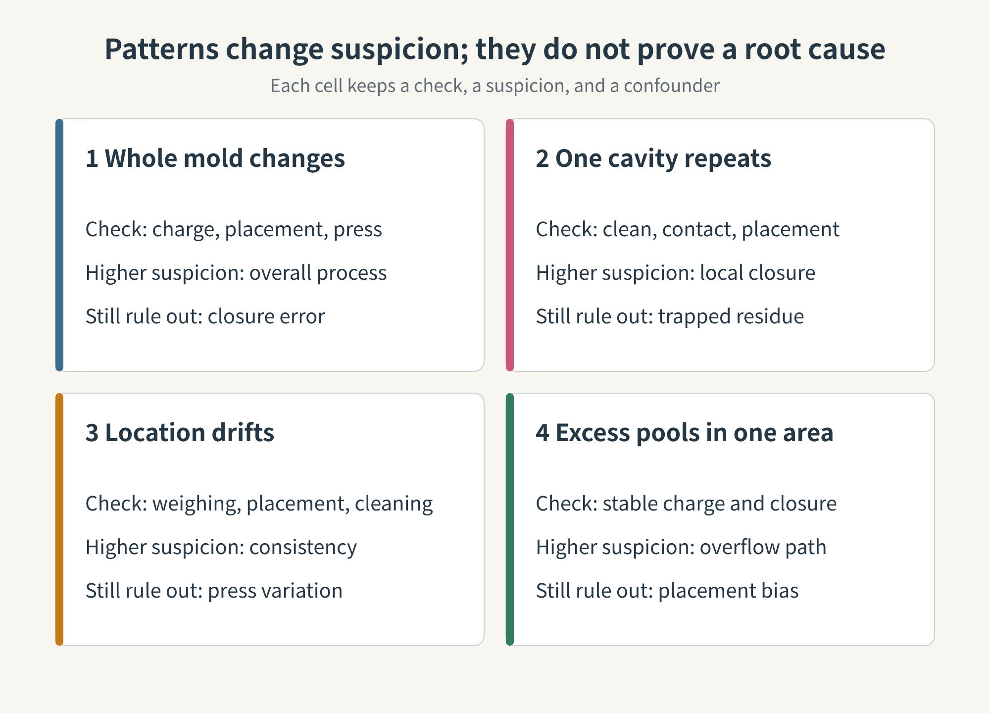
Arranging the samples is a way to decide what to inspect next, not a way to declare a root cause from a location chart. Flash in compression molding can be influenced at the same time by charge weight, preform shape and placement, mold design and fit, closing pressure, compound flow, and cure condition. The same visible result may come from several variables acting together.
If all cavities develop flash at the same time and the flash changes with charge weight or placement, the charge and loading method become stronger suspects. Before reducing the charge, however, still verify press condition, overall mold closure, and the basic molding settings. A mold-wide change does not prove that every parting surface is sound.
If one cavity or one local area develops the same flash over several consecutive cycles, first inspect parting-surface cleanliness, contact marks, damage, load support, and the charge path for that cavity. A fixed location makes a local closure issue more likely, but it does not prove that the mold surface is worn. A preform placed off-center over many cycles or residual rubber trapped repeatedly at the same point can leave a similar pattern.
If the flash location drifts from cycle to cycle, first check weighing, preform placement, trapped material, cleaning, operator consistency, and press condition. When charge weight and mold closure are stable but excess rubber continues to accumulate in one area, add the overflow path, blockage, and tear-off structure to the next inspection.
Mixed patterns also occur. Flash may be excessive across the whole mold while one cavity has a much thicker area at the same location. Do not force this into a single explanation. First hold charge weight, placement, and press conditions constant for the full mold. Then investigate cleanliness, contact, and charge placement for the exceptional cavity. Separating the mold-wide change from the local difference shows which factor explains the overall condition and which one explains only the single-cavity anomaly.
Change the Charge First Only When Two Conditions Are Met
A small, controlled charge adjustment is a suitable first trial only when two conditions are met. First, the flash must change with charge weight, preform shape, or charge placement. Second, cleaning, trapped material, alignment, and local closure checks must show no stable, fixed abnormality. If either condition is missing, do not reduce the charge simply because the mold appears to contain too much rubber.
In each trial, change only one of these variables: charge weight, preform shape, or charge placement. Keep the other two variables constant, along with the compound batch, main molding conditions, and cavity-sampling method. Use the same identification system for samples before and after the change. Do not look only for less flash. Check whether the flash location, thickness, and residual edge change with the adjustment and whether the profile in every cavity remains fully filled.
Too much rubber can increase excess material at the parting line, while too little can cause underfill, incomplete local filling, or an incomplete profile. If underfill appears, a critical dimension deteriorates, or the sealing result becomes unstable, stop the trial and return to the previous baseline. There is no universal charge-reduction percentage for this situation. The step size must be set according to part volume, compound behavior, and the capability of the existing process.
Evaluate the Overflow Groove When Excess Rubber Has No Controlled Path
An overflow groove gives excess rubber a controlled destination. It manages where the excess material travels and whether the resulting flash can be removed cleanly. It cannot make an open or poorly mating parting surface close correctly. A vent provides an escape path for gas in the cavity. An overflow groove receives rubber that crosses the flash land. A tear-off groove helps the flash separate during post-processing. The flash land is the narrow region between the cavity edge and the overflow groove that controls the thin flash section. These four features serve different functions and should not be treated as one type of groove.
Before evaluating an overflow-groove change, confirm three points: charge weight and placement are stable; basic parting-surface contact is acceptable; and excess rubber still accumulates in the same area, tears unpredictably, or encounters a blocked or ineffective overflow path. If these conditions are not met, enlarging the groove may change the visible symptom without showing that the closure issue has been corrected.
After a structural change, check more than the overflow and trimming result. Verify that the cavity still fills completely, venting behavior has not deteriorated, tear-off does not damage the part, and the functional sealing edge remains intact. No single groove width, depth, or volume applies across different compounds, parts, and mold configurations. Dimensions from another project should not be copied directly.
Work on the Parting Surface Only After a Local Defect Repeats
The parting surfaces mate when the mold closes, and modifying them is the least reversible of the three actions discussed here. Move to spotting, fitting, or repair only after cleaning when the same cavity and the same location still produce a repeated projection or mismatch, and when contact marks, diagonal measurements, or other checks also indicate local loss of contact, damage, or uneven load support.
Stop if the defect cannot be reproduced, the contact check does not match the flash location, or the proposed correction would cut into a datum or the cavity profile. A fixed location is not a substitute for measurement, and the mold surface should not be stoned or polished by experience alone. Public technical sources also do not support a universal amount of material to remove.
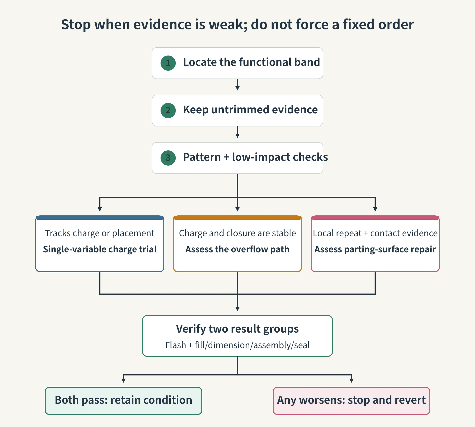
In terms of reversibility, a small charge trial is easiest to undo. An overflow-structure modification is harder to reverse. Spotting or repairing the parting surface is the hardest to restore to its previous state. This order describes increasing difficulty of reversal and the need for stronger evidence. It does not mean that every project must reduce the charge first, modify the groove second, and repair the surface last. When the evidence for a fixed local closure defect is strong enough, parting-surface work may be the correct direct action. When the evidence is weak, none of the three should be changed together.
Less Flash Does Not Mean the Work Is Finished
After a change, review at least two groups of results. The first group covers flash location, thickness, residual edge, and the profile after trimming. The second covers filling completeness, critical dimensions, assembly, and sealing function. The change is acceptable only when both groups pass. Otherwise, the adjustment may simply have moved the defect elsewhere.
Before-and-after comparisons must follow the same recording rules. If the baseline uses untrimmed samples but the changed condition is judged only from carefully finished parts, the appearances are not comparable. If the assembly condition or operating conditions of the sealing test have changed, the difference cannot be attributed entirely to the mold adjustment. Keep baseline samples, samples after the change, and samples after trimming. They answered three separate questions: how the flash changed, what trimming left behind, and whether function was maintained.
| Result After the Change | How to Interpret It |
|---|---|
| Flash improves while filling, dimensions, assembly, and sealing remain stable | Keep this condition and the comparison samples, then continue confirmation according to the project requirements. |
| Flash improves, but underfill, dimensional deviation, or sealing instability begins | Reverse the change. The defect has shifted rather than been corrected. |
| Flash shows no stable change and the sample pattern does not repeat | Add cavity, cycle, charge, and closure records before making further mold changes. |
| A fixed local defect repeats and the contact check points to the same area | Only then evaluate spotting or repair of the corresponding parting surface. |
You cannot decide in advance which item to change without examining the samples. If flash is confined to an outer edge, address appearance and trimming quality first. If the pattern follows charge weight or placement, begin with a reversible charge trial. If charge and closure are stable but the overflow path remains uncontrolled, evaluate the overflow structure. If flash repeatedly returns at a fixed location and the contact check points to the same area, then address the parting surface. When the evidence is still incomplete, retain more samples and continue recording. Do not change all three items at once merely to make the surface look cleaner.