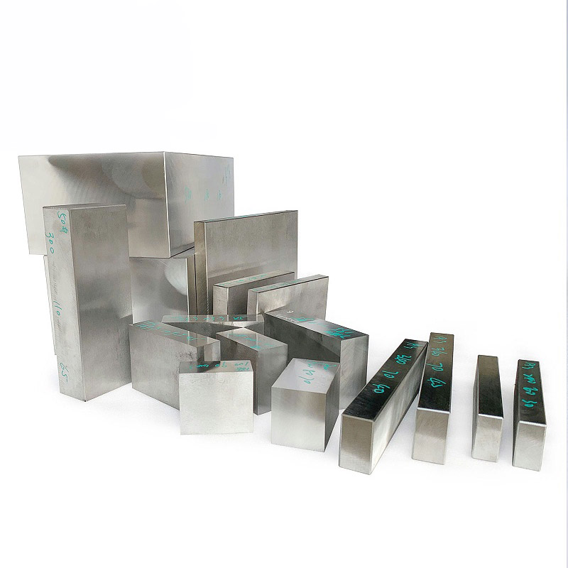
As of September 14, 2026, one supplier listing on Made-in-China still priced a single-cavity electronic housing mold, producing one part per cycle, at US$3,000–4,000. The page did not explain how the two housing halves would be molded, which flame-retardant PC grade would be used, how the plug pins would be assembled, how mold life would be defined, or what the mold trials and dimensional inspection would cover. This is one supplier’s advertised price, not a Chinese market range, and it cannot be applied directly to a charger housing.
A mold quotation should not be judged by its total price first. This tutorial uses a two-piece 65 W USB-C charger housing as an example. It measures approximately 55 × 50 × 30 mm, has a USB-C opening in the upper housing and two plug pins in the lower housing or rear cover, and is based on an annual volume of 100,000 sets. A local A-surface requires a better cosmetic finish, while ejector-pin marks are permitted on non-visible surfaces. These assumptions explain the evaluation method only. They do not describe a customer project or an existing product made by moldsteells.
Step 1: Mark Five Areas on the Product
Start with the product, not the number of cavities. Locate five areas on this housing: the USB-C opening in the upper housing, the joint between the two housing halves, the plug-pin area, the visible A-surface, and the non-visible surface where ejector-pin marks are acceptable. Unless these areas are identified, terms such as “high gloss,” “plug pins,” and “parts per shot” do not define a clear quotation scope.
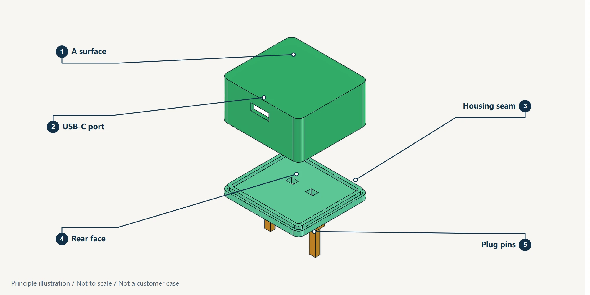
Add the information that the picture cannot show. Specify the exact resin grade and color for the housing, mark the actual wall thickness and ribs on a section, show how the two halves are assembled at the joint, and circle the dimensions to be measured around the USB-C opening and housing interfaces. “Flame-retardant PC” describes a material family, not a complete quotation condition. A change in resin grade or wall thickness changes cooling shrinkage and may also affect sink marks and gloss, so the mold steel and cooling layout must be reassessed.
When we at moldsteells review drawings for an Injection Mold like this, we first check the molding relationship between the upper and lower housings, the plug-pin relationship, and the acceptance scope. We then perform DFM, which checks whether the product can be manufactured and molded, and mold flow analysis, which simulates plastic filling and cooling. If a discrepancy appears, it can be traced to a specific area of the drawing instead of being described vaguely as “a problem with the charger housing mold.”
Step 2: Decide How the Two Housing Halves Will Be Molded
This housing consists of an upper and a lower half. First determine whether both will be molded simultaneously in one mold or produced in separate molds. Placing one cavity for each half in the same mold is commonly called a 1+1 family mold. The decision is not simply about which option is cheaper. The real question is whether the gates, cooling, and process adjustment for both parts can be handled together in one mold.
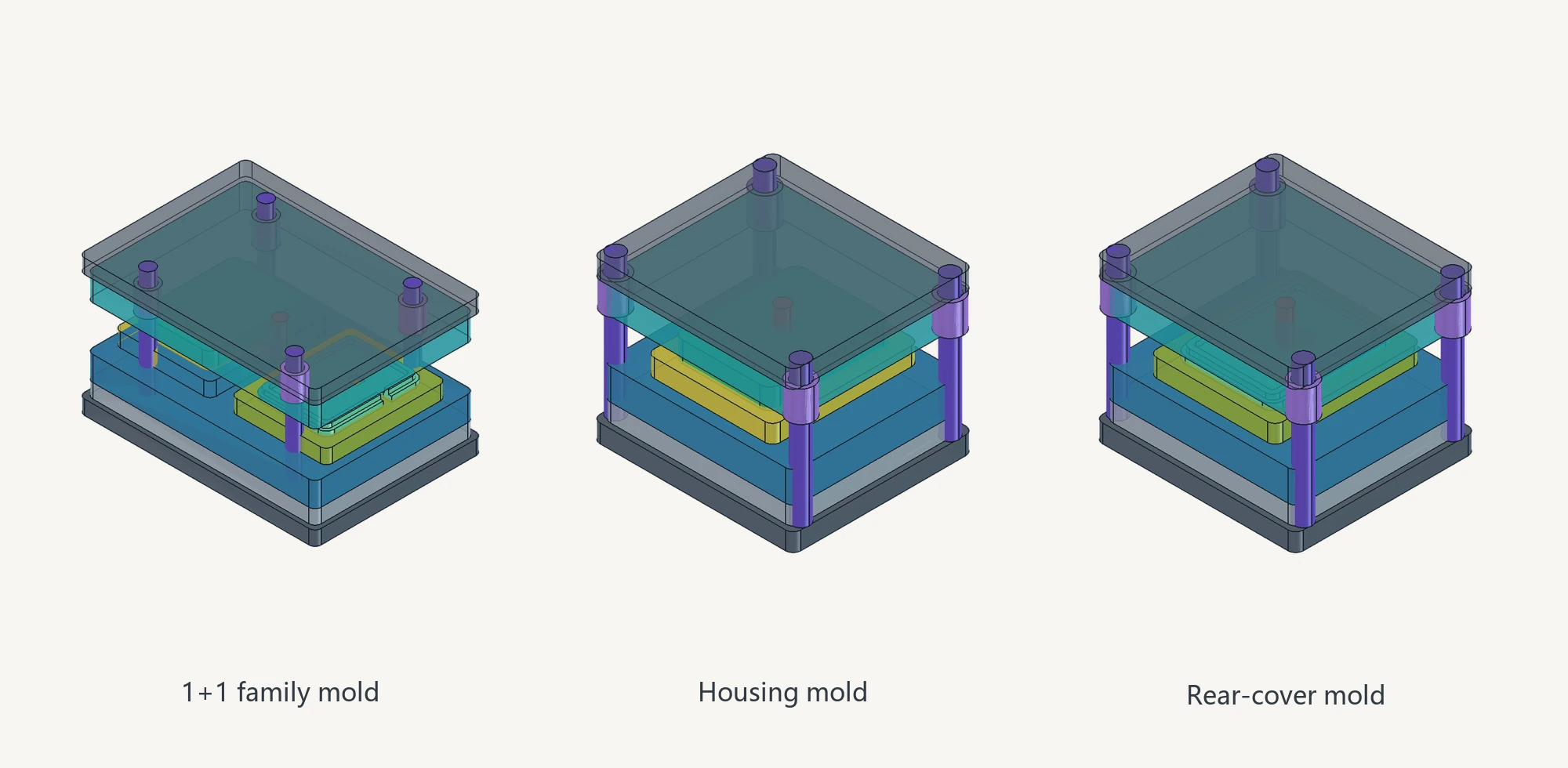
If the two parts fill and cool differently in a family mold, each part must be checked separately for dimensions, appearance, and fit during the mold trial. A mold correction for one part may also affect the other. Separate molds require an additional molding solution at the outset, but their gates, cooling, and process settings can be handled independently. This is the difference between a quotation for “one mold for the complete housing” and one for “two separate molds for the upper and lower housings.”
At this stage, check only one result: do both quotations use the same molding arrangement for the two housing halves? If one assumes a family mold and the other assumes separate molds, their total prices are not yet directly comparable.
Step 3: Compare Single-Cavity and Multi-Cavity Options
Only after the molding arrangement has been confirmed should you ask how many identical parts each cycle will produce. A single-cavity mold produces one upper or lower housing per cycle. A multi-cavity mold produces several identical upper or lower housings per cycle. An annual volume of 100,000 sets does not automatically require multiple cavities. Volume alone does not reveal the cycle time, available molding machine, resin, order variability, or the dimensional requirements of each housing half.
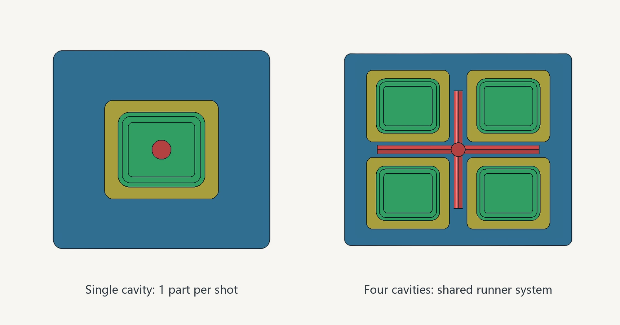
Adding cavities also requires a coordinated runner, gate, and cooling layout. Even with a symmetrical layout, parts from different cavities may not fill equally. During mold trials, keep the cavity ID with each sample and its inspection data. This separates a problem in one cavity from a condition affecting the complete molding process. Cavity-level traceability should also cover the A-surface: inconsistent appearance across cavities cannot be accepted by inspecting only one sample.
When comparing quotations, separate the initial mold manufacturing cost from the molding cost allocated to each housing. With stable demand, multiple cavities may reduce the unit molding cost but will usually increase the upfront mold manufacturing cost. If one quotation includes a multi-cavity runner, cooling system, and cavity-by-cavity inspection while the other assumes a single cavity, the two total-price lines are not directly comparable.
Step 4: Confirm the Plug-Pin Relationship in Section
Seeing “two plug pins” on the product does not tell the moldmaker how the mold should be built. Examine a section showing the relationship between the metal pins and the plastic housing. The pins may be positioned inside the mold and encapsulated with plastic, assembled after both housing halves have been molded, or accommodated by side openings, retaining features, or clearance in the housing. These three situations must be evaluated separately.
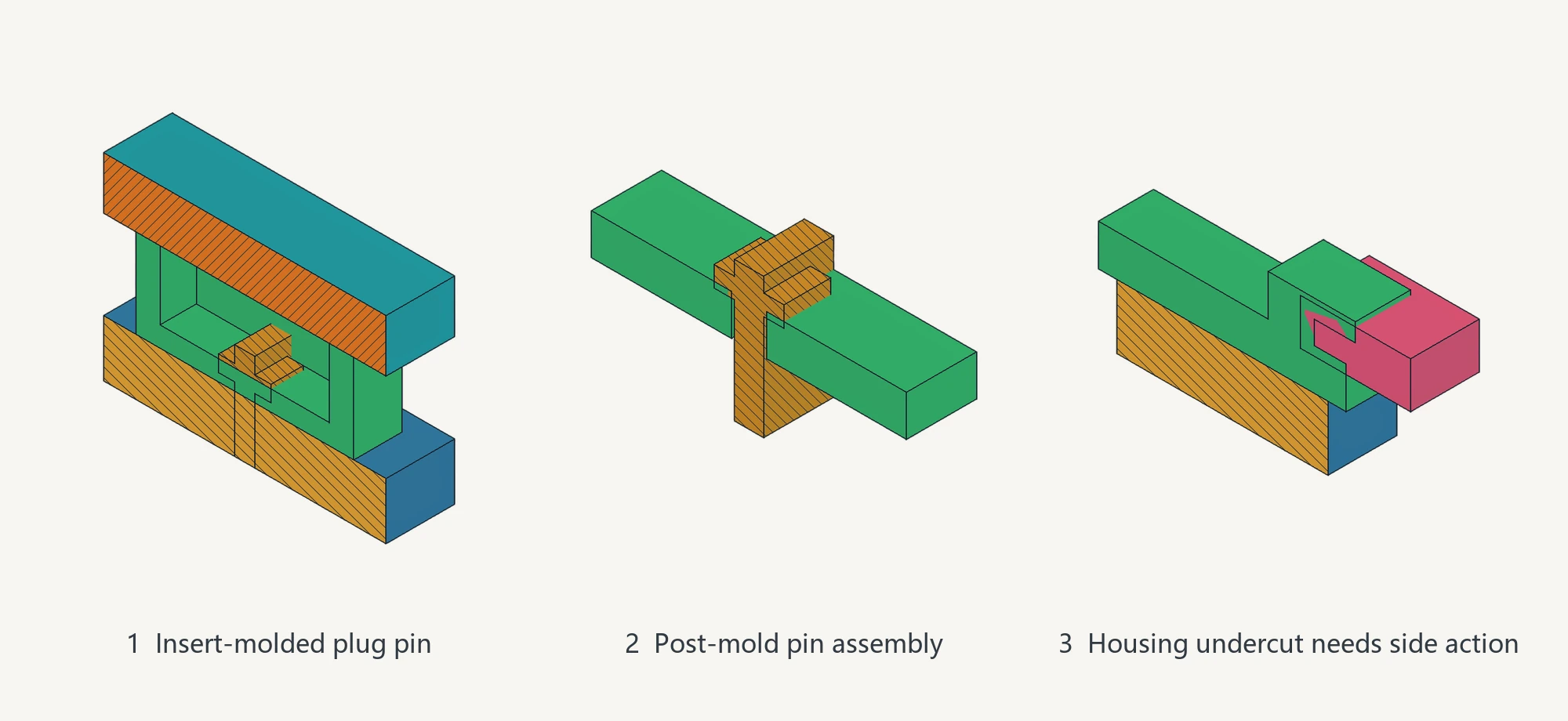
For insert molding, the metal pins are placed in the mold before plastic is injected around them. The review must establish how the metal is located, where the plastic should encapsulate it, and whether the shutoff boundary can be formed. For post-molding assembly, the critical items are the opening position, locating clearance, and assembly space.
If the housing has a side opening, retaining feature, or undercut, first determine whether the part can be released completely along the main mold-opening direction. This is a straight pull. If interference prevents a straight pull, evaluate a side action that retracts laterally during mold opening. An insert, a different parting-line position, or a draft on the sidewall may also remove the interference.
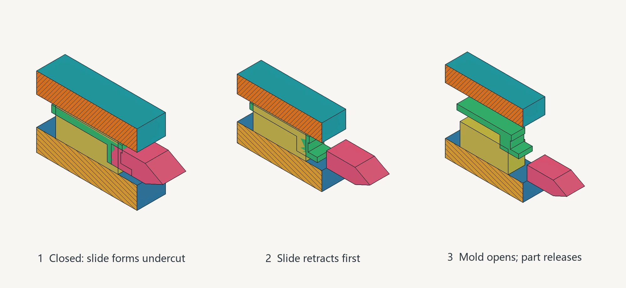
Therefore, a quotation line stating “plug-pin structure included” cannot be compared by itself. Confirm that both suppliers priced the same pin assembly method. If the assembly relationships differ, the total prices describe different mold actions.
Step 5: Define the A-Surface and Then Define Mold Life
“High gloss” is not enough to define the A-surface. Mark whether the cosmetic area is around the USB-C opening, on the front of the upper housing, or somewhere else. Then specify the desired finish and inspection method. The drawing should also state whether a parting line, gate vestige, or ejector-pin mark is permitted on the A-surface and its transition areas. Ejector-pin marks may be acceptable on non-visible surfaces, but they must stay away from the A-surface.
The area requiring mold polishing follows the A-surface definition. In Guangdong moldmaking, this work is often called sheng mo (省模): the cavity surface is progressively stoned, corrected, and polished where necessary until the agreed cosmetic result is reached. It does not mean applying the same finish to the entire mold. If an ejector position falls on the A-surface or the parting line crosses a visible area, the mold layout and part structure must be reconsidered. A single universal draft angle cannot be applied in advance, and “the entire mold is high gloss” should not be treated as the default.
Mold life cannot be defined by a shot count alone. The quotation or life agreement should identify at least five items: the exact resin grade and additives, mold steel configuration, cooling arrangement, maintenance responsibility, and the method used to record cycles. Resin, continuous operation, surface requirements, and cooling stability together affect wear, corrosion resistance, and finish retention. Without these operating conditions, neither the steel selection nor the life commitment can be checked.
The flame-retardant PC grade for this example has not been specified, so neither a mold steel grade nor a fixed mold life can be assigned. “Cooling channels included” is also insufficient. Temperature stability around the upper housing, lower housing, and A-surface must be observed in the molding plan and during mold trials. A quotation that provides only a cycle count does not define mold life until the resin grade, steel, cooling, and maintenance conditions are added.
Step 6: Separate Mold Trials from Dimensional Inspection
T0 is the first mold trial. For this sample housing, first check whether the upper and lower parts fill, release, and assemble correctly. With multiple cavities, retain the cavity ID on every sample. T1 follows corrections made after the previous trial and checks the resulting appearance and critical dimensions. The number of trials, sample quantity, and sampling method depend on the dimensional, cosmetic, and assembly characteristics defined on the drawing; they should not be fixed in advance.
Dimensional inspection compares agreed-upon samples with the drawing. A coordinate measuring machine (CMM) inspection or full-dimensional report can verify the USB-C opening, housing interfaces, and identified dimensions. It does not replace complete-product electrical safety, charging performance, or long-term life certification. Separating mold trials, dimensional inspection, and complete-product certification makes it possible to determine whether a failure comes from the product design, molding conditions, or dimensional acceptance criteria instead of grouping everything under “acceptance included.”
How to Align Two Mold Quotations
The table below omits prices and aligns six scope items line by line.
| Item to Compare | Quotation A | Quotation B | What You Can Conclude First |
|---|---|---|---|
| Upper and lower housings | One 1+1 family mold | Separate molds for the two housing halves | The quotations assume different molding arrangements. |
| Number of cavities | Single-cavity | Multi-cavity, without defining the runner, cooling, or cavity-level inspection | Complete the scope before judging whether the multi-cavity option is more or less expensive. |
| Plug pins | Assembled after molding the two halves | Metal plug pins encapsulated by insert molding | The assembly relationship and mold actions differ. |
| Visible surface | States only “high gloss” | Defines the A-surface around the USB-C opening and restricts ejector-pin marks | Quotation B has a clearer scope, but the finish target and acceptance method are still required. |
| Mold life | States only a cycle count | Defines the resin grade, mold steel, cooling circuits, maintenance responsibility, and cycle-recording method | Quotation B defines the operating conditions more completely, but a fixed life still cannot be promised. |
| Mold trials and dimensions | States only “acceptance included” | Defines T0/T1, critical dimensions, appearance, and samples identified by cavity | Quotation B defines the inspection objects more clearly; the project still determines the quantities. |
The purpose of this table is not to select the supplier with the lower total price. It is to confirm whether both suppliers priced the same product and the same set of requirements. Return to the product drawing and confirm the molding arrangement for both housing halves, plug-pin relationship, resin grade, A-surface boundary, and inspection objects. Prices become comparable only after both quotations describe the same work. Mark these product features first and then align the process scope item by item to see exactly where the cost difference comes from.