Fine cracks appear on the mold cavity surface before the tool reaches the shot count expected for the project. During the review, the material certificate identifies the steel as H13, and its hardness is within the specified range. Why has it still cracked early?
To answer that question, first consider what the surface experiences in each casting cycle. Molten metal heats it, while casting removal and spraying cool it. The surface layer and the interior are connected, but they do not expand and contract in step. This mutual constraint creates thermal stress, which can lead to thermal fatigue cracks under repeated cycling.
From moldsteells’ perspective on manufacturing Die Casting Molds, the review also needs to connect the insert’s steel, heat treatment, and service location. The explanation below starts with how the damage develops, then examines the evidence that can help diagnose early cracking.
How does heat checking develop under repeated heating and cooling?
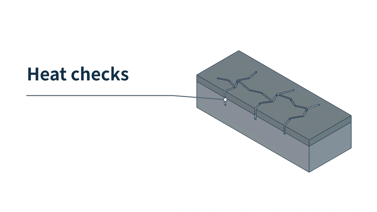
Heat checking usually begins as fine cracks on the mold cavity surface. As cycling continues, the cracks may multiply, join into a network, and deepen into the steel. This is thermal fatigue damage. Large cracks extending through an insert, metal adhesion, and pits caused by erosion need separate investigation. They should not be classified as the same problem simply because they all occur on the mold surface.
Start with a single piece of steel. Orange and blue in the diagram represent the surface layer during heating and cooling, while gray represents the connected interior. These are different regions of the same steel body. The colored bands are not coatings or measured temperature fields. The arrows show the direction of compressive or tensile stress acting on the surface layer, not its actual movement. The third panel shows crack development after repeated cycles.
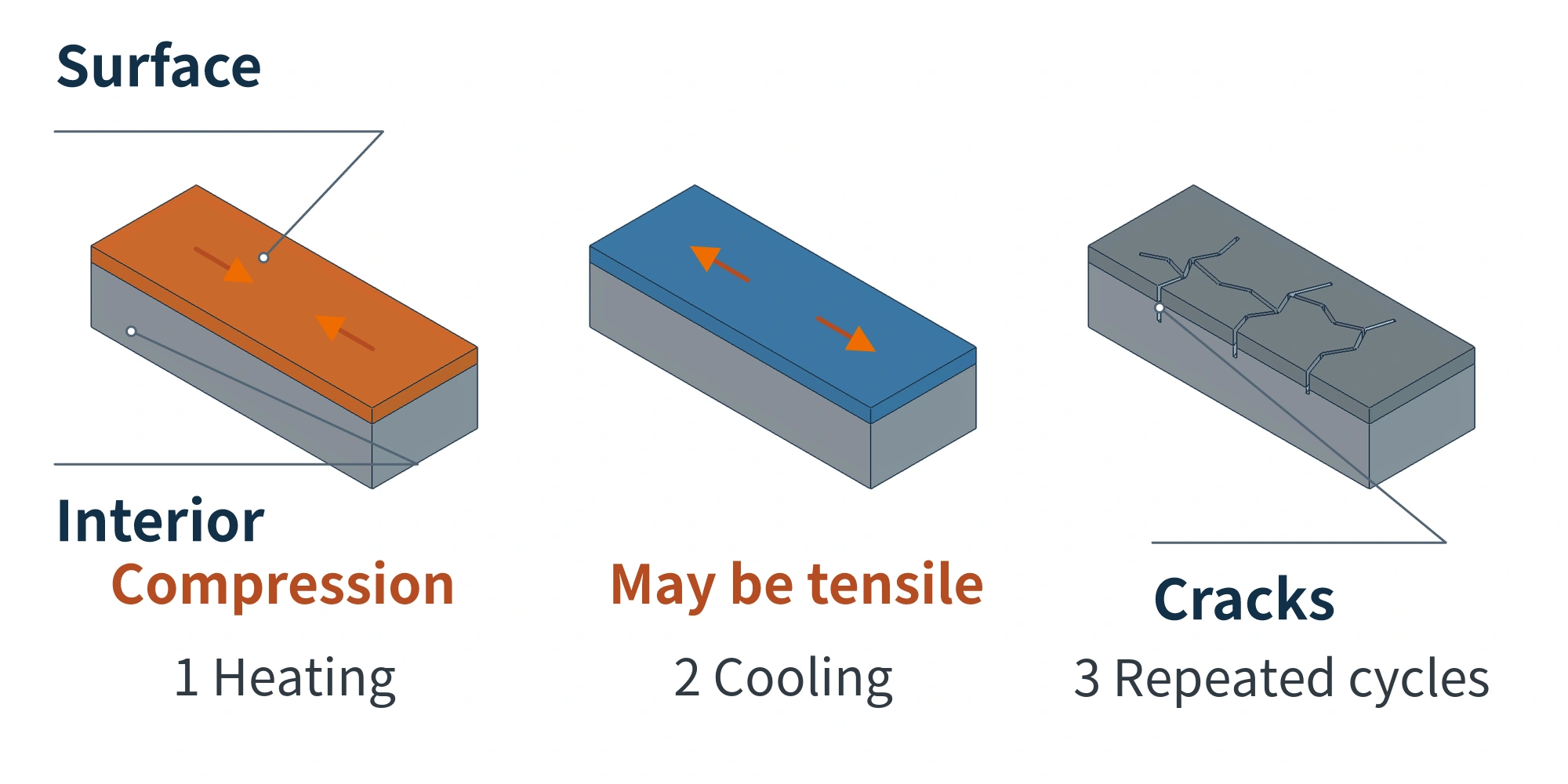
Stage 1: The surface heats up, but the interior restrains its expansion. When molten metal contacts the mold cavity, the surface layer heats first. The temperature change in the interior lags behind. The surface layer tends to lengthen, but it is connected to interior steel that has expanded less. It cannot expand freely, so compressive stress develops. This stress comes from constrained deformation within the steel and should not simply be equated with injection pressure.
The stress level at which steel begins to deform permanently is called its yield strength. If the local stress exceeds the steel’s yield strength at that temperature, plastic deformation occurs. Here, “permanent” means that the deformation does not fully recover when the stress is removed. It does not necessarily mean that a visible depression has already formed on the mold surface.
Stage 2: The surface cools, but its contraction is also restrained. After the casting is removed, the surface begins to lose heat. Spraying a water-based release agent accelerates surface cooling as the water evaporates. The interior may not have cooled at the same rate. The surface tends to shorten, but the still-hotter interior, which has contracted less, restrains it. The original compressive stress may decrease and become tensile stress.
Whether the stress becomes tensile depends on the temperature difference between the surface and interior, the degree of constraint, and the material’s existing deformation state. Under some thermal cycling conditions, the stress remains compressive after cooling. Every cooling stage should therefore not be depicted as necessarily producing tension.
Stage 3: Fine cracks initiate locally, then grow under further cycling. The next filling stage heats the same region again, and casting removal and spraying cool it again. The surface repeatedly experiences this constrained deformation.
The steel also contains local variations. For example, nonmetallic substances trapped in the steel are known as inclusions. Their thermal expansion and other properties differ from those of the surrounding steel. During heating and cooling, the two deform differently, so forces can concentrate in the neighboring regions. If repeated loading causes local plastic deformation, microcracks may initiate at these locations. This is one possible initiation mechanism, not evidence that inclusions cause all heat checking.
Once fine cracks have appeared, the same region continues to undergo thermal cycles. If tensile stress develops during cooling, it can drive existing cracks to grow. As cycling continues, cracks lengthen, join into a network, and may deepen into the steel. An initial fine crack and the network seen later are therefore different stages of progressive damage. It is damage that accumulates. The stress values from successive cycles cannot simply be added together as though the steel cracks when a total pressure is reached.
This cycling can be reproduced in a test. In a study published in Special Casting & Nonferrous Alloys, Chen Jianhong and colleagues used an 80 mm diameter steel specimen with induction heating and spray cooling. Heating to 600°C and then cooling to 150°C counted as one cycle. The thermocouple measurement point was 20 mm from the heated end face. These were the conditions of a particular specimen and measurement location, not temperature settings to apply directly to a production mold surface. An actual review needs temperature records for the same location on the current mold at stages such as after filling and after spraying.
Why do some locations crack first?
Different areas of the same mold differ in how they contact molten metal, dissipate heat, and are shaped. The surface cycling described above therefore does not occur everywhere at the same time or to the same extent.
Near the gate, examine how molten metal contacts the mold surface. If a region receives concentrated heat input and direct metal impingement, compare the crack initiation area with the filling direction. Early cracking there is a reason to investigate local thermal loading and impingement. Proximity to the gate alone does not establish that the steel is nonconforming.
In sprayed areas, examine how the surface cools. A region that receives concentrated spray may have a different surface-to-interior temperature change from an adjacent region that is not sprayed in the same way. Cooling-channel location and actual coolant flow also affect heat removal. Compare temperatures at the same stage of the cycle. Do not compare a reading taken just after spraying in the cracked area with a reading taken just after filling elsewhere.
At hole edges, sharp corners, and machined or repaired areas, examine local loading and surface condition. Changes in geometry can concentrate stress. Processes such as electrical discharge machining and repair welding may also leave a surface or microstructure different from that of the surrounding base metal. If cracks first follow these areas, review the corresponding machining and repair records, then verify the findings by examining the actual insert.
Location tells you where to investigate first, but it cannot establish the cause on its own. For example, early cracking in a repair-welded area may involve both a different post-weld microstructure and more severe local thermal cycling. Excluding either factor can lead to a premature conclusion.
Why can the same steel grade and hardness give different thermal fatigue resistance?
H13 is a steel grade. It cannot replace the quality records for the actual piece of steel. Hardness primarily describes resistance to indentation. Toughness concerns the material’s resistance to cracking and fracture under load. The two properties answer different questions.
Hardness is related to strength and affects how readily the steel undergoes plastic deformation. However, a conforming hardness value does not reveal every inclusion in the steel or fully represent the microstructure and toughness across the entire insert section. Simply increasing hardness is therefore not a universal remedy for early cracking.
First, examine the steel itself. Chemical composition, nonmetallic inclusions, and microstructural uniformity affect its ability to withstand repeated thermal stress. The material certificate, cleanliness examination, and ultrasonic testing each have their own scope. Passing one does not substitute for the others. In particular, ultrasonic testing that finds no defects exceeding the acceptance limit does not establish that microstructure or toughness has been verified as conforming.
Next, examine the Heat Treatment this piece of steel actually underwent. During quenching, the interior of a large-section insert may cool more slowly than its surface. CINDAS technical data for H13 explains that the cooling path affects the resulting microstructure and carbide distribution, and that some unfavorable structures reduce toughness. Subsequent tempering also changes the microstructure, residual stress, and balance between strength and toughness. A final hardness result within the specified range therefore does not establish that the entire section underwent an appropriate treatment process.
The North American Die Casting Association (NADCA) also lists hardness, microcleanliness, ultrasonic testing, microstructure, and impact capability as separate steel quality criteria in its public overview. Heat treatment has additional requirements covering quenching, microstructure, hardness, and impact properties. These requirements address high-volume or critical-performance applications. They show why different types of evidence need separate verification, not that every die casting mold must adopt an identical set of criteria.
Cross-check crack location, steel heat number, and heat-treatment furnace load
The first step in a review is to establish which insert is affected, where the cracks occur, and when they were first observed. Photographs should allow the area to be located relative to the gate, a hole edge, or another reference feature. Record the shot count at the time of the photograph and subsequent changes. If cracks are already present at the first inspection, that establishes only that they had appeared by then. The inspection shot count is not the exact crack initiation count.
“Early” also needs a reference. State which project expectation the cracking precedes, what quality change defines the endpoint, and whether the comparison is with historical molds for the same product under similar production conditions. The cycle count at which a test specimen develops its first microcrack cannot be converted directly into a required production mold life.
The second step is to link the records to that insert. The steel heat number identifies the steelmaking batch; the heat-treatment furnace load identifies a later batch loaded into a furnace for treatment. Steel from the same heat can be heat-treated in separate loads, and one heat-treatment furnace load may contain steel from different heats. The two identities must be traced separately.
| What to compare | Evidence linked to this insert | Question it answers |
|---|---|---|
| Steel | The link between the raw steel cut piece and insert identification; steel heat number and material certificate; applicable cleanliness, ultrasonic, and microstructure records | Does this piece of steel have the corresponding material quality evidence, and do abnormalities follow the same steel batch? |
| Heat treatment | Insert identification linked to the furnace load; actual temperature measurement locations and curves; quench-cooling and tempering records; corresponding hardness, microstructure, or toughness results | What treatment did the insert actually undergo, and are there shared abnormalities within the same furnace load? |
| Service location | The earliest confirmed crack area and shot count; temperatures at the same cycle stage; cycle timing, spray and cooling conditions; machining or repair-weld locations | Does cracking recur with a particular local cycle, geometric feature, or repair area? |
A heat-treatment temperature curve also needs a clear measurement identity. Furnace temperature, insert surface temperature, and temperature measured inside the insert are different quantities. A curve reaching its setpoint does not by itself establish the internal temperature and cooling path of a thick section. If the record lacks measurement locations or a link to the insert, identify that gap.
The third step is to test the suspected cause against the comparisons, rather than assigning responsibility as soon as one abnormality appears.
- Different steel batches or heat-treatment loads still crack first at the same location: Investigate that location’s heat input, spraying, cooling, and geometry first. If temperature and operating records also show an abnormality, the local-service-condition explanation has stronger support. Material examination still needs to remain part of the review; location alone cannot rule it out.
- Abnormalities across different locations or molds cluster within the same steel batch: Verify the material-to-insert links, then examine the actual cleanliness and microstructure results. If the abnormalities instead follow a particular heat-treatment furnace load, focus on its temperature measurement, quenching, and tempering process. Sharing a steel grade does not mean sharing the same material quality.
- Cracks follow a machined or repair-welded area: Compare the crack initiation location with the machining or repair area. Examine the possible effects of the surface layer, microstructure, and residual stress, while also reviewing local thermal cycling. Distinguish cracks present before repair from cracks found again afterward; they cannot all be recorded as new cracks.
These comparisons establish the order of further investigation. Supporting a particular cause requires agreement between location, timing, and examination of the actual insert. If material and furnace-load records cannot be linked, or temperature and operating records before and after crack initiation are unavailable, the conclusion should remain “not yet determined.” What to obtain next depends on whether the gap concerns material quality, the heat-treatment process, or local cycling.
References
Chen Jianhong et al., research and application of processes to reduce cracks in die casting molds, Special Casting & Nonferrous Alloys, 2020, Vol. 40, No. 8; Ding Hai et al., failure analysis of aluminum-alloy die casting molds and measures to improve service life, 2014, Vol. 34, No. 9; NADCA public overview of recommended procedures for die steel; CINDAS technical data for H13; the 2021 Mechanika study on a thermal fatigue model for aluminum-alloy die casting H13 dies; and the 2025 review of thermal fatigue failure mechanisms in die steels in the Journal of Materials Research and Technology.