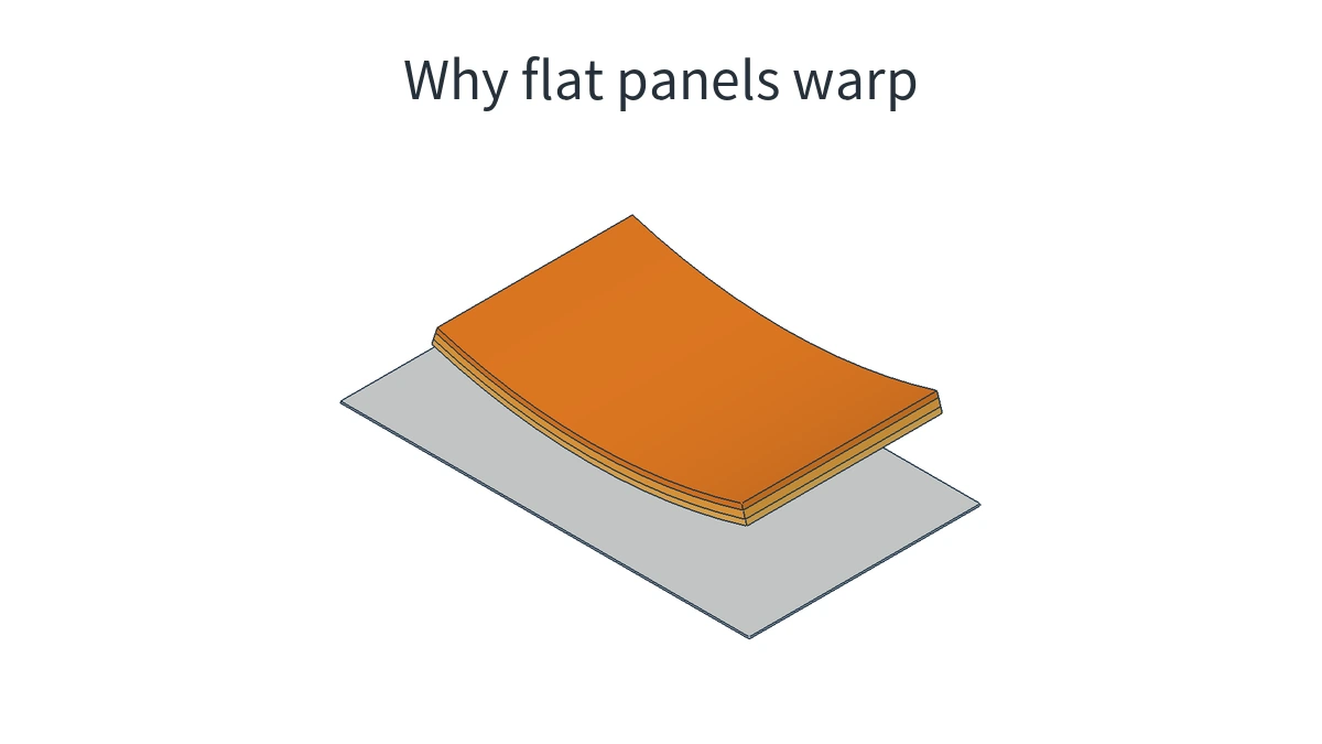
When evaluating a trial-molded sample of a large appliance housing, a plastic panel designed to be flat may bow in the center or lift at two corners, making assembly gaps difficult to keep consistent. The subject here is the plastic part formed in the mold: what happened during filling, packing, and cooling, and why can it no longer stay flat after leaving the mold?
The answer lies within the part. Regions near the gate and at the far end, directions along and across the flow, and the two sides through the thickness may shrink differently. These portions remain connected, so they cannot each shrink to the dimensions they would otherwise reach. Following the molding process of the same panel makes it possible to trace its final curvature back to the causes that produced it.
Why do some flat panels simply shrink while others warp?
Plastic generally loses volume as it changes from a melt to a solid. If all regions and directions of a panel shrink in a compatible way, the panel can remain flat, with only its dimensions changing. Warpage becomes a concern when some portions of the same part tend to shrink more than others.
For example, consider the panel through its thickness. The plastic near one face may tend to shrink more than the plastic near the opposite face. Because the two sides are connected, the side that shrinks less restrains the other side from shortening; the side that shrinks more also pulls on the other. This mutual restraint leaves internal stresses, and the panel may bend to change the relationship between the lengths of its two sides. If the differences between regions are asymmetric, twisting may also occur.
The plastic also shrinks while it is inside the mold. The mold walls, mold core, and adjacent material that has already solidified restrict some dimensional changes and bending. After demolding, these constraints change, and the remaining internal stresses redistribute, potentially making the deformation more apparent. Seeing a corner lift only after the part leaves the mold does not mean the differences that caused it first arose at that moment.
The next three types of difference concern the direction of flow, the regions reached by additional melt during packing, and the two sides through the part’s thickness.
How does the gate create directional differences during filling?
Melt enters the mold cavity through the gate and spreads into regions that have not yet filled. Changing the gate location also changes the paths the melt takes through different regions. The local flow directions at the center, edges, and end of the flow path are not necessarily the same.
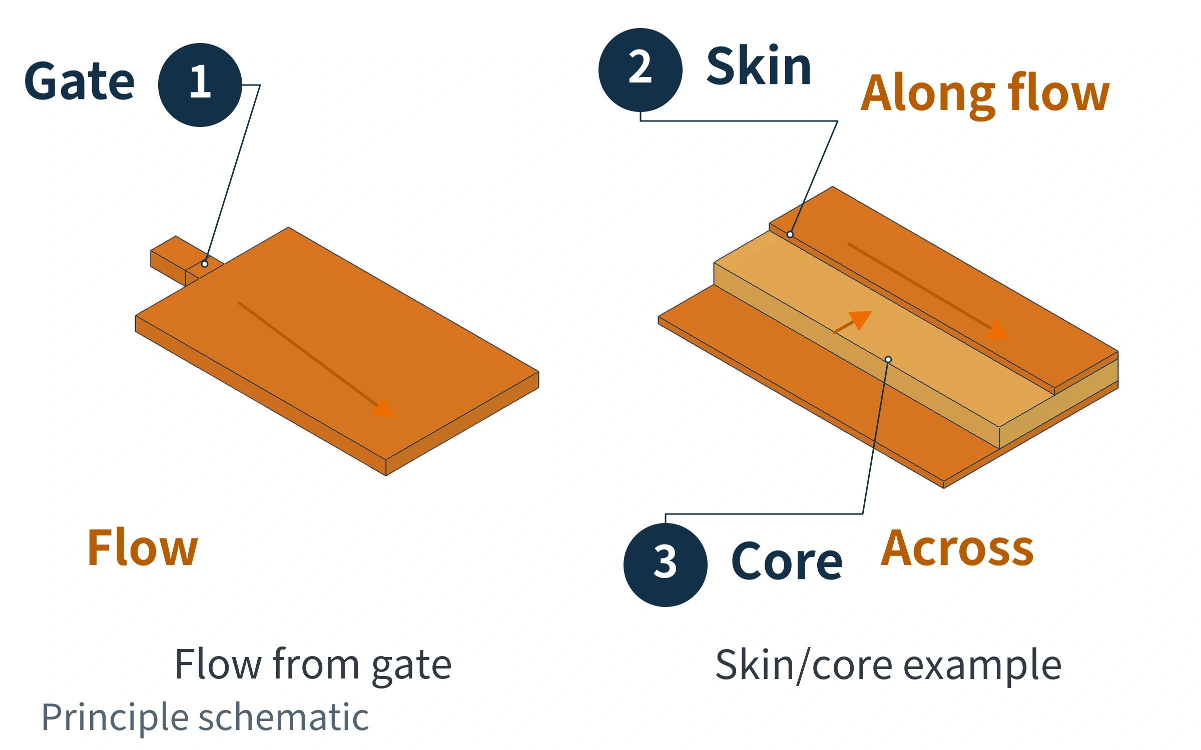
Flow can create directional differences even without glass fibers. Polymer chains that were initially more coiled and oriented in various directions become stretched during flow and align more closely with the local flow direction. This is called orientation. After flow stops, the chains gradually relax toward a more coiled state, and the length they previously occupied along the orientation direction may contract.
How much of this dimensional recovery occurs before solidification, and how much orientation and stress remain, depend on the material and its cooling history. The retained portion may continue to relax after demolding. Orientation therefore affects the direction and progression of dimensional change; it cannot be reduced to a rule that all unreinforced plastics shrink more along the flow direction. Final shrinkage also reflects pressure, cooling, crystallization, and other effects.
Glass-fiber-reinforced plastics have an additional source of directional differences: once fibers align in a particular direction, they more strongly restrain the plastic from shortening in that direction. Shrinkage along the fibers may therefore differ from shrinkage perpendicular to them.
The cross-section through the thickness in the illustration also requires a distinction between the skin and core. In a thicker panel, fibers in the skin may predominantly align with the flow, while those in the core may tend to align across it or have a random orientation. Different locations within the same part also have their own orientation distributions. The fibers do not remain uniformly parallel throughout the entire panel and its full thickness.
When connected regions experience different directional restraints, they have difficulty shrinking compatibly. This is how the gate affects warpage: a change in the flow path changes orientation, which changes directional shrinkage. The actual direction of bowing also depends on the resin grade, wall thickness, ribs, and subsequent pressure and cooling histories.
Why do regions near the gate and at the far end receive different amounts of melt during packing?
After the mold cavity fills, the plastic continues to cool and lose volume. As long as the melt in the gate and along the path to the target region can still flow, the packing pressure applied by the screw can compact the material and deliver additional melt into the mold cavity to compensate for this volume loss.
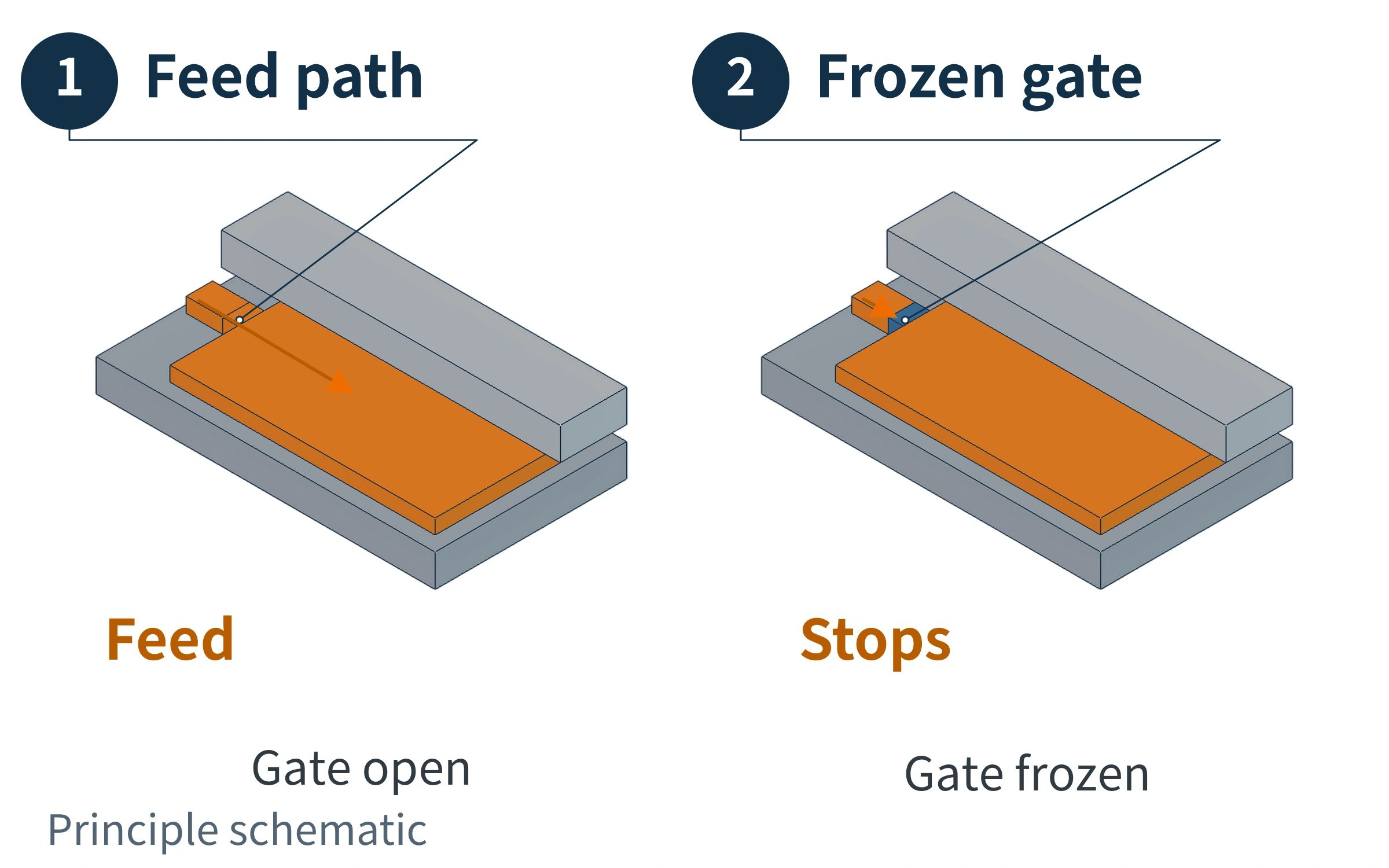
A single packing pressure setting on the machine does not mean every location in the panel experiences the same pressure. Melt encounters resistance as it passes through the gate and the flow paths within the panel, while cooling and solidification continually change the cross-section available for flow. Regions farther from the gate may receive less effective melt feeding than regions near it and may consequently shrink more afterward.
The near and far regions may therefore shrink by different amounts. Different amounts of shrinkage do not, however, mean the panel must warp: connected regions can sometimes accommodate the differences through changes in their in-plane dimensions or shape.
If the shortening required by each region cannot be accommodated simultaneously in a single planar shape, their connection restrains them from shrinking independently. Portions that tend to shorten more are held back by neighboring material, while other portions are also constrained, generating tensile or compressive stresses within the panel. In a thin panel, compressive stress may also destabilize the flat configuration, causing it to bow or twist out of plane. Whether this deformation occurs depends on the panel’s geometry, stiffness, constraints, and stress distribution. Any difference in shrinkage between the near and far regions should not automatically be treated as a confirmed cause of warpage.
Melt feeding also has a time limit. A section of a thin-walled flow path may solidify first, making it difficult for downstream regions to continue receiving melt. Once the gate freezes off, the path for feeding melt into the part through that gate closes. Extending the machine’s packing time beyond this point will not add more material to the part through that gate. Gate freeze-off does not, however, mean the entire part has finished cooling or that pressure inside the mold cavity immediately drops to zero.
Observing part weight at different packing times can help identify when additional melt feeding stops. With the other conditions held stable, a transition from increasing weight to a plateau is one indication that the gate has sealed. It records the net amount of material added to the whole part; it does not prove that every region of the panel has been packed uniformly.
How does unequal cooling on the two faces turn shrinkage differences into bending?
Cooling begins as soon as the melt contacts the mold walls, overlapping with filling and packing. The panel’s two faces contact the mold walls on either side. Heat passes from the plastic into the steel mold and is then removed through the cooling channels. Differences in the distance from the channels to the molding surface, local heat accumulation, and actual coolant flow can give the plastic on the two sides different solidification histories.
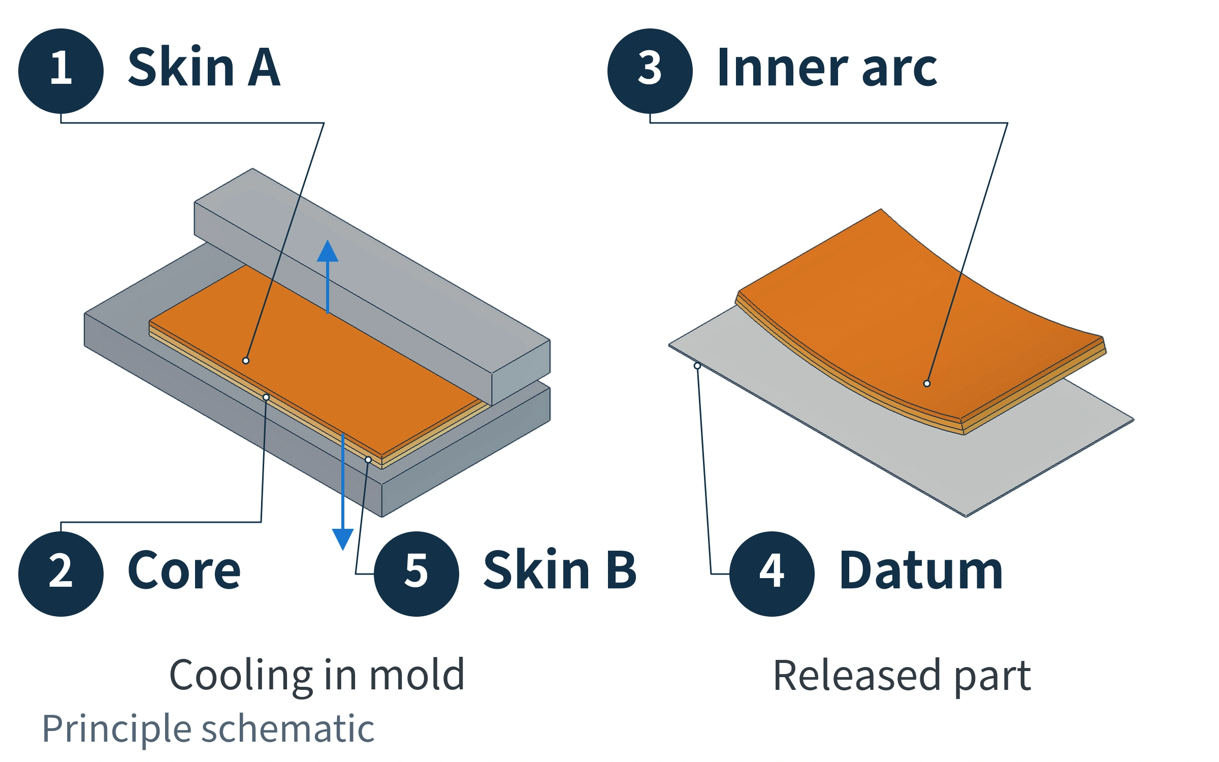
Start with the cross-section through the thickness on the left. The plastic near both the upper and lower mold walls generally forms solidified skin layers first, while the inner core remains able to flow for a period of time. The solidified layers gradually grow inward from both faces. Differences in heat transfer between the two sides may also change how the skins develop and when the individual layers solidify.
The plastic has been continuous from the outset. While the core can still flow, some deformation can be accommodated by flow and relaxation. As more material solidifies, the layers that solidified earlier restrain the free shortening of layers that form later. The actual shortening of each layer therefore depends on its own cooling as well as the constraints imposed by the surrounding material and mold walls. If the shrinkage histories retained on the two sides through the thickness are asymmetric, they may create a tendency for the panel to bend.
Now consider the curved panel on the right. Suppose that, along the same direction, the upper and lower portions would end up at different lengths if they were not restrained by each other. In reality, they are connected and cannot remain straight while simultaneously reaching those two lengths. Bending places the side with the shorter free length on the inner arc and the other side on the longer outer arc, accommodating part of the length difference through a change in shape. Demolding changes the mold-wall constraints, which may allow this bending to become more apparent.
The shorter inner arc corresponds to the shorter final free length. The side that solidifies first does not necessarily shrink more, and the side that is hotter at a particular moment does not necessarily become the final inner arc. Actual housings are also affected by orientation, regional melt feeding, and ribs, and may continue to change after demolding. Predicting the direction of bending requires considering these processes together.
For semi-crystalline plastics, crystallization also matters. Different cooling histories change the degree of crystallinity that develops during molding, as well as any crystallization and shrinkage that may still occur afterward. This also explains why two groups of samples should be compared after the same storage time, rather than directly comparing a freshly demolded part with one that has been left to stand.
How can you trace a warped panel back to its causes in the molding process?
Keep track of the sample’s gate location, core side, and cavity side, and record where it bows and which corners lift, using the same measurement datum. This makes it possible to relate the final shape to the locations where differences arose during molding. Recording only a single value for “maximum warpage” loses the spatial relationships between the near and far regions and between the two faces.
| Difference to explain | Evidence that can be related to the process | What that evidence does not establish |
|---|---|---|
| Different shrinkage in different directions | Actual filling paths and orientation analysis, particularly local and skin/core fiber orientation in glass-fiber-reinforced materials | A single overall flow arrow cannot predict the bending direction of the entire part |
| Different amounts of melt feeding in different regions | Mold cavity pressure histories near the gate and at the far end, together with packing time and changes in part weight | Stable part weight does not prove that all regions shrink equally |
| Different solidification histories on the two sides through the thickness | Mold-wall temperatures at corresponding locations on the two sides, actual cooling-channel connections, and cooling records | Identical temperature-control settings on both sides do not prove that the two mold surfaces experienced the same conditions |
The three types of difference interact. For example, cooling narrows the paths through which melt can still flow, changing subsequent melt feeding. Changing packing pressure also changes both material compaction and internal stress. An improvement in flatness after increasing packing pressure therefore shows only that the shape responded to that change; it does not establish insufficient packing pressure as the sole cause.
In a 2017 coupled simulation study, Jiang Qingsong and colleagues examined a thin-walled, center-gated housing made from polypropylene reinforced with 30% glass fiber. They found that warpage increased with packing pressure in the model with a 1 mm wall thickness. The study discussed the effects of restricted melt feeding in thin walls and increased internal stress. This counterexample, obtained under specific material, geometry, and simulation conditions, reminds us to distinguish “reducing shrinkage” from “reducing warpage.” It cannot be turned into a rule that packing pressure should be reduced for all large flat panels.
A gate modification should explain what changed in flow and orientation. A packing adjustment should explain which regions can still receive additional melt. A cooling modification should explain whether the solidification histories on the two sides have become more compatible. Relating these changes back to the shape of the same part is how you can determine whether a modification addresses the stage of the process that caused the warpage.