
When you receive a 3D model and first-article inspection report for a security camera front housing, do not begin by checking whether every dimension is marked green. Put the lens board or PCB location, front-housing lens bore, perimeter sealing interface, and fastening points on the same assembly drawing. Then ask one question: do the drawing, the coordinate measuring machine fixture, and the final assembly all establish their coordinate system from the same physical faces, holes, or slots?
If they do not, a conforming lens-bore position and sealing-face flatness can still produce an off-center image or a water leak after assembly. In this article, coaxial alignment means that the axis of the lens bore aligns with the functional axis of the lens barrel and lens in the assembled condition. Position tolerance limits the bore axis relative to the theoretically exact location defined by a datum reference frame. The two are related, but they are not interchangeable. The bore and sealing interface are also affected by the same filling, cooling, shrinkage, and fastening conditions. Datums A, B, and C below are a general engineering example. Each project must confirm the actual mating and locating features in its CAD model.
Why Can a Dimensionally Conforming Housing Still Leak or Misalign the Image?
Start with a simple action: place the front-housing CMM report, inspection fixture, and final assembly drawing side by side. Mark the datums used for the lens bore, sealing interface, and fastening points. The question is not whether each number falls within tolerance. The question is whether those numbers can be compared within the same physical datum reference frame.
The first failure mode is a different measurement origin. The drawing may establish the coordinate system from a stable mating face and locating hole on the front housing, while the fixture supports the part on a separate cosmetic surface. A green CMM report then does not prove the assembly relationship. First align the drawing datums, fixture contacts, and assembly location, and then measure the part again. Do not modify the mold first.
The second failure mode is an unstable datum feature. The parting line is the boundary where the two mold halves separate. Lateral mismatch between the halves creates a mold-shift step, while a thin excess edge forms flash. If a datum face crosses the parting line, mismatch and flash can tilt the datum contact before any downstream measurement begins. Lens-bore position and sealing-face flatness are then measured from an origin that can move, so different reports will not agree. Choose a stable surface formed entirely by one mold half, or revise the parting strategy, before discussing tolerances.
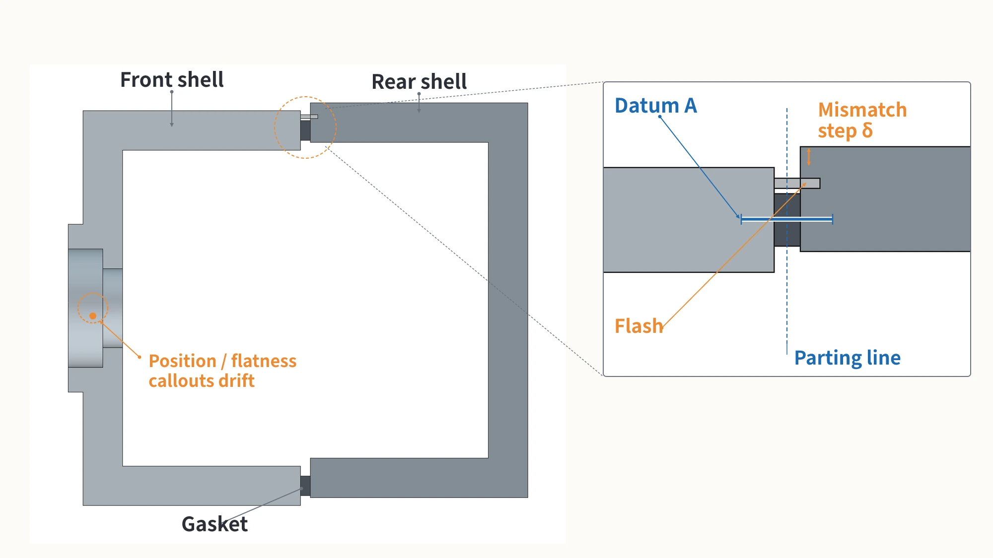
The third failure mode is shared deformation after Plastic Injection Molding. Plastic contracts as it cools, but a thick flange, a thin sealing rib, and material flowing in different directions do not shrink by exactly the same amount. Gate and cooling layouts can amplify the difference. The sealing interface can warp, and the lens bore or lens counterbore can move with it. If the datum setup is repeatable but lens-bore position or sealing-face flatness is out of tolerance, inspect the core, cavity surface, gate, cooling circuit, post-mold shrinkage, and warpage direction.
The fourth situation occurs when the geometry passes inspection but the assembly still fails. Fastener load travels through screw bosses and mating faces into the housing. O-ring contact also changes local loading. No camera-specific deformation value can be cited here, so the first check must remain qualitative: confirm even screw tightening, compatibility between O-ring cross-section and groove depth, and any local lift at the sealing interface. Then decide whether to change the assembly condition or correct the mold.
This section produces a checkable result: the reports use the same datums, the datum features are stable, and geometric error has been separated from assembly loading. If any of these points remains unclear, “all dimensions are green” is not yet a valid conclusion.
Where Should Datums A, B, and C Be Established?
Identify the complete product relationship before assigning datums. The front housing includes a seating face for the camera module or lens board. The board has a primary round hole and a secondary locating slot. The center of the front housing contains a lens bore or lens counterbore. A sealing groove and sealing interface run around the perimeter, with fastening points nearby. Datums A, B, and C must be placed on physical features that can be contacted, fixtured, and measured repeatedly. “Use a common datum” is not enough.
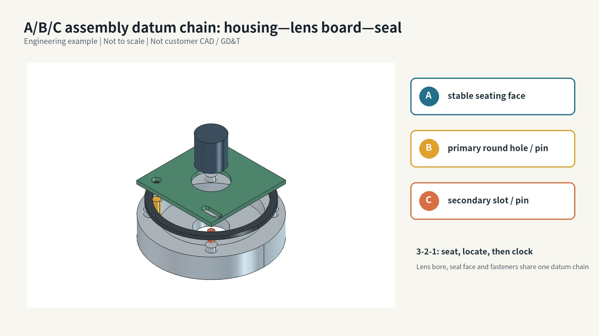
One practical engineering arrangement is:
- Place datum A on the stable seating face for the camera module or lens board. It constrains translation normal to the face and rotation about the two in-plane axes, for three degrees of freedom. Datum A must relate to the real assembly interface and sit reliably on an inspection fixture. A face that crosses the parting line, is strongly affected by gate shrinkage, or is formed jointly by both mold halves is a poor primary datum.
- Use the primary round hole and a round locating pin near the optical axis as datum B. This constrains translation in two in-plane directions. Keeping B close to the functional lens location shortens the dimensional chain among the lens board, lens bore, and lens barrel. If the real design locates on a cylindrical register or lens-barrel seat instead, use that functional feature rather than forcing a pin-and-hole scheme.
- Use the secondary locating slot and pin as datum C. It constrains the remaining in-plane rotation. Clearance in one slot direction can accommodate thermal expansion and keep dimensional variation from accumulating until the parts bind. That accumulation is tolerance stack-up. Two round holes used as simultaneous locators can overconstrain the assembly. If the CAD model contains only two round holes, first determine whether one should become a slot that releases one direction.
This is the familiar 3-2-1 location principle: three, two, and one degrees of freedom are constrained in sequence. The name matters less than confirming that all six degrees of freedom are controlled without redundant constraint. On the 3D model, you should be able to point to every datum contact, show how the fixture touches it, and identify which assembly component reuses it.
After defining A, B, and C, perform a disassembly check. Remove the rear housing and seal, leaving only the front housing and lens board. The three datums should still locate the lens board repeatably. Reinstall the seal and rear housing, and the sealing interface must remain measurable in the same reference frame. If the datums exist only after the complete enclosure is closed, a CMM fixture will usually struggle to reproduce them. If the disassembled lens board can still move in-plane, datum B or C is not actually locating it.
Once A, B, and C are fixed, relate the functional features to them. Control the lens bore or counterbore with position or surface profile relative to the datum reference frame A-B-C. Locate the fastening points from the same frame. Flatness controls only the sealing surface itself and does not reference a datum. If the surface must also be oriented or located relative to A, B, and C, select parallelism, perpendicularity, or a datum-referenced surface profile according to function, and state the datum order. Only then can CMM results correspond to the final assembly instead of relying on a separate measurement frame chosen merely for convenience.
During our design-for-manufacturability review at moldsteells, we place the physical datum features used by design, mold manufacturing, CMM inspection, and assembly on the same drawing. Mold-flow analysis, mold trials, and the full-dimensional report then continue from those same features.
The acceptance test for this section has three parts: every datum points to a physical feature; all six degrees of freedom are constrained without overconstraint; and the primary datums avoid crossing the parting line or being split between mold halves whenever possible. If the lens seat is a long cantilever, the housing span is unusually large, or the real location method is not a seating face plus pin and slot, stop applying this example and recalculate the structure, deformation, and gauge scheme from the project CAD.
Mold Tolerances Need Upstream Margin
Do not assign the product’s complete functional tolerance directly to the Plastic Injection Mold. Core and cavity manufacturing introduce variation before molding adds material shrinkage, uneven cooling, and process variation. Glass-fiber-reinforced engineering plastics also shrink anisotropically because fibers align with the flow. If mold manufacturing consumes the entire tolerance, no margin remains for molding variation.
First connect each functional product feature to its mold-side control. Then decide where tighter control is justified:
| Product Feature and Inspection Item | Product-Side Specification | Corresponding Mold Control | What to Check After a First-Article Failure |
|---|---|---|---|
| Lens-bore axis location | Defined by the project drawing. If cylindrical position is used, state the cylindrical tolerance zone relative to A, B, and C. If X/Y bilateral controls are used, state each direction separately. | Reallocate core-position tolerance using the same expression. Do not interchange a plus/minus tolerance with a diametrical position tolerance. | Core assembly, gate and cooling layout, post-mold shrinkage, and warpage |
| Sealing-interface flatness | Project drawing value; flatness does not reference a datum | Reserve upstream margin for the cavity surface according to material, geometry, machining capability, and first-article feedback | Cavity surface, wall-thickness differences, cooling balance, and local deformation after fastening |
| Datum features A/B/C | As defined by the project drawing | Form them in one mold half and keep them clear of the parting line and flash | Fixture repeatability, mold mismatch, flash, and datum stability |
| Nonfunctional cosmetic areas | Normal production accuracy | Do not tighten them simply because a functional area is tight | Address only actual cosmetic or assembly failures |
The table intentionally gives no universal project-independent numbers. A cylindrical position tolerance defines a cylindrical tolerance zone, while X and Y dimensions use independent bilateral tolerances. They cannot be converted directly. State the functional result required from the finished part first, and then allocate upstream mold margin using the same tolerance convention. Project values depend on material, wall thickness, span, gate and cooling design, manufacturing capability, and the actual assembly requirement.
Mold-side action cannot rely on a fixed ratio alone. Before cutting production mold steel, use mold-flow analysis to predict shrinkage and warpage directions. After the mold trial, use CMM data to correct the core, cavity, or process conditions. When glass-fiber orientation is significant, simulation and trial data must replace a fixed rule. If the first-article deviation follows the predicted direction, correct the relevant functional feature. If the direction changes between runs, stabilize the process and measurement state before removing or adding mold steel.
Record the measurement condition as well. A plastic part continues to shrink after ejection, so data taken immediately after molding cannot be compared directly with data taken after full conditioning. In this project workflow, T0 means the first mold trial, used mainly to confirm stable molding and record process conditions. T1 means the next trial after the first mold correction, used to verify dimensional and structural changes. These labels identify trial rounds, not two measurement times, and suppliers may use different numbering. Measure under the temperature, humidity, conditioning time, and fixturing conditions stated on the drawing, and use the same state for each trial round and the first production sample. If conditions differ, standardize them and remeasure before calling the mold out of tolerance.
The acceptable result is not a drawing on which every tolerance has been tightened. Functional features have a tolerance budget, nonfunctional areas avoid unnecessary cost, and each Mold Tooling control has a corresponding first-article inspection item. If an item cannot be found in the report, the tolerance remains only a drawing note and has not become a verifiable mold requirement.
CMM, Leak Testing, and IP Testing Are Not Interchangeable
Verification should follow the same product objects through the process. CMM inspection establishes the component geometry of the front housing, lens bore, and sealing interface. A leak test provides a production screening result at a defined threshold. Ingress protection testing verifies whether the complete enclosure meets the required water-ingress condition. Each answers a different question, and passing one does not prove the others.
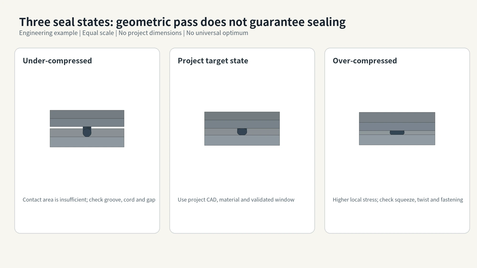
First define the sealing condition. For an axial static seal, calculate the compression ratio as (d-h)/d × 100%, where d is the O-ring cross-section diameter before assembly and h is its remaining height in the compression direction after the housing is closed. Insufficient compression can leave a leakage path, while excessive compression can cause permanent deformation. Global O-Ring’s summary of Parker static-seal guidance gives approximately 15%-25%, and Marco Rubber’s face-seal guidance gives 20%-30%. Therefore, 15%-30% is only a conditional reference range for an axial static seal. The actual window must be defined from material, cord diameter, groove depth, sealing-face geometry, and the project’s test specification; it is not a universal optimum.
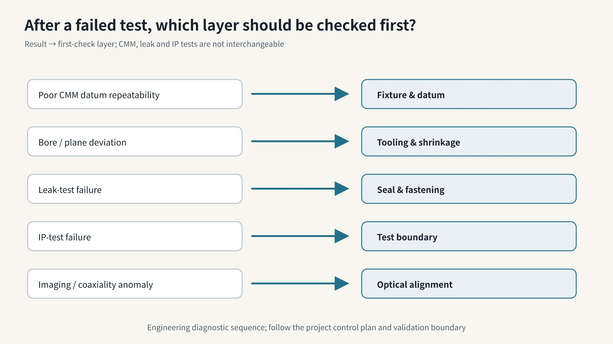
Use the five result categories below to organize the first investigation. They are not mutually exclusive root causes. If you already have evidence of cracks, cable-entry leakage, or a lens-window joint failure, inspect that path in parallel.
- The CMM cannot establish A/B/C repeatably, or repeated measurements drift. Check fixture contacts, whether datum A crosses the parting line, whether the fixture rests on flash or a mismatch step, and whether the datum face itself is warped. Suspend downstream geometric conclusions until the coordinate system is stable.
- A/B/C are repeatable, but lens-bore position or sealing-face flatness is out of tolerance. Return to the core, cavity surface, gate, cooling circuit, post-mold shrinkage, and warpage. Then confirm that the part was remeasured under the same conditioning state after the mold trial.
- CMM results pass, but the leak or IP test fails. Check O-ring cross-section, groove depth, actual compression, sealing-interface flatness, fastening load, and assembly condition. Conforming component geometry does not prove that seal contact stress is adequate.
- The production leak screen passes, but the IP test fails. Check the leak threshold, hold conditions, and actual immersion boundary. Under the IPX7 conditions in IEC 60529, the specimen is immersed completely for 30 minutes in the service position specified by the manufacturer. If the enclosure height is less than 850 mm, its lowest point is 1,000 mm below the water surface. If the height is at least 850 mm, its highest point is 150 mm below the surface. Water must not enter in a harmful quantity or impair normal operation. The 1,000 mm and 150 mm values are alternative placement rules selected by specimen size, not a single fixed depth for every product. Confirm the applicable standard edition and specimen size for the project.
- Component geometry and enclosure sealing pass, but the image is still abnormal. For image-center or optical-axis offset, inspect the location of the lens module, lens barrel, and sensor. If the geometric center is correct but the image is out of focus, check the focus setting and any focus shift after adhesive application or locking. Stop tightening housing tolerances here; the investigation has moved into optical assembly.
Before release, the reader should be able to complete this checklist on the project documents:
- ☐ The 3D model identifies the physical face, hole, or slot for each datum A, B, and C and states the degrees of freedom that each constrains.
- ☐ The lens bore or counterbore, sealing interface, and fastening points all use the same A-B-C datum reference frame. Flatness is not confused with datum-referenced orientation or location control.
- ☐ Product functional requirements, mold controls, and CMM inspection items correspond one by one, without indiscriminately tightening nonfunctional areas.
- ☐ The CMM report states the fixture datums and measurement condition, and repeated coordinate-system establishment is stable.
- ☐ Leak and IP results each state their own test conditions and acceptance criteria. IPX7 conditions have been checked against specimen size rather than substituted for one another.
- ☐ Every failure result has a primary investigation step. Image-center offset and defocus lead separately to assembly location and focus-lock checks, while parallel root-cause paths remain open.
At this point, “balancing lens alignment and waterproofing” becomes a result that can be identified on the product drawing, allocated backward into the mold design, and checked again in the inspection report. The sequence is clear: confirm physical datums first, allocate functional tolerances second, and then investigate CMM, leak, IP, and imaging results level by level.