Quotes for a phone case mold can range from $12,000 to over $37,000—a threefold difference. When the drawings specify a wall thickness of 0.6-0.8 mm and a mirror-finish high-gloss surface with Ra ≤ 0.05 μm, most 3C product buyers get stuck on three real questions: Can this be done in a single molding step? Do we need a post-molding spray coating process? Where does the money go, and what costs can be cut?
Here’s the bottom line: The “trilemma” of thin walls, a high-gloss finish, and high precision isn’t a single technical problem. It’s an interplay of four factors: gate design, cooling channel layout, mold polishing, and hot runner control. If any one of these is off, the mold will produce glossy but non-conforming parts plagued by weld lines, warpage, and sink marks. Whether you can achieve a one-shot molding process depends on getting all four right simultaneously. Miss one, and you’ll face mass rejections during production ramp-up. This article breaks down whether it can be done, how to do it, which costs are non-negotiable, and how to evaluate a supplier.
1. Thin Walls Are More Than Just Material Reduction
The mainstream wall thickness for phone cases is 0.6-0.8 mm. This might sound “a bit thinner than usual,” but it’s fundamentally a flow dynamics problem. Conventional plastic parts have a wall thickness of 2-4 mm; 1.2-2 mm is considered “advanced,” and anything under 1.2 mm is “leading-edge.” For a 0.5 mm thick part, the solidified layer on each side can be 0.2 mm, leaving only a 0.1 mm channel for the molten plastic to flow through. The material freezes before it can fill the mold cavity.
Therefore, the process parameters for thin-walled parts are an order of magnitude different from conventional parts:
- Injection Speed: 400-2000 mm/s (vs. 50-200 mm/s for conventional parts)
- Injection Pressure: 1500-3000 kg/cm² (vs. 700-1000 for conventional parts)
- Mold Temperature: 60-150 °C (depending on the material)
- Holding Pressure: 2-4 stages, with pressure decreasing in each stage
These parameters aren’t just pulled out of thin air by the mold maker. They’re based on an industry rule of thumb: allow 0.5-1.0 seconds of holding time for every 0.1 mm of wall thickness. For a 0.8 mm phone case, this puts the holding time in the 4-8 second range.
Another often-overlooked factor is the L/t ratio (flow length to thickness). When this ratio exceeds 200:1, multi-stage injection becomes mandatory. A 0.8 mm thick phone case with a flow length of 160 mm is right on the edge, which is why a multi-stage velocity profile is standard, not optional.
| Parameter | Thin-Wall Phone Case | Conventional Injection Part | Difference |
|---|---|---|---|
| Injection Speed | 400-2000 mm/s | 50-200 mm/s | 5-10x |
| Injection Pressure | 1500-3000 kg/cm² | 700-1000 kg/cm² | 2-3x |
| Holding Pressure Stages | 2-4 stages | 1 stage | Multi-stage profile |
| Mold Temperature | 60-150 °C | 40-80 °C | 20-70 °C higher |
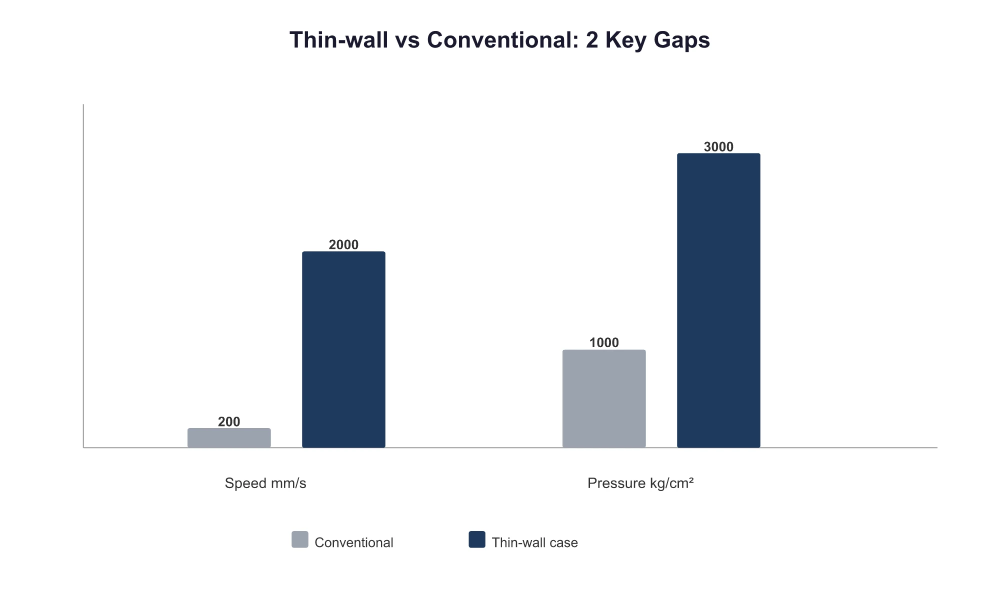
Thin-wall molding isn’t about simply using less material; it’s a flow dynamics challenge. If a mold maker quotes you based on a machine designed for conventional injection speeds, the mold will be useless from the first shot.
2. The Four-Step Process for High-Gloss Shells
The standard process flow for a high-gloss phone case involves four steps:
- Material Feeding — The raw material (PC, PC+GF, PMMA, etc.) is dried and plasticized into a molten state by the screw.
- Injection Filling — The mold closes, the plastic fills the mold cavity, and holding pressure is applied to compensate for shrinkage before cooling.
- Cooling and Solidification — The mold is cooled, and the plastic solidifies. This is where the process diverges: either RHCM (Rapid Heat Cycle Molding) or conventional cooling.
- Surface Finishing — If step 3 produced a mirror-finish, high-gloss part (using RHCM), it’s ready. If it’s just a standard glossy surface, it goes for spray coating.
Key takeaway: Spray coating is step 4, happening after injection molding, not before. RHCM is a process upgrade in step 3, not the opposite of spray coating. The two routes differ in mold cost by 25-30%, with a 6-12 month difference in investment payback period.
Route A: One-Shot Molding with RHCM (Using Rapid Heat Cycle Molding in step 3): The mold is first heated to 20-30 °C above the material’s glass transition temperature (Tg)—120-150 °C for PC, 90-110 °C for PMMA. After the plastic fills the cavity and the holding phase is complete, the mold is instantly cooled to 30-40 °C. This adds 15-25% to the cycle time, but it eliminates the need for spray coating in step 4.
Route B: Conventional Molding + Post-Process Spray Coating (Using conventional cooling in step 3 + spray coating in step 4): The mold is 25-30% cheaper, but you need a spray coating line. This means an initial investment of $300,000+, dealing with fluctuating yield rates, and navigating environmental approvals for VOC emissions. The coating itself also ages and can peel, yellow, or show silvering after 3-5 years.
| Dimension | RHCM One-Shot Molding | Conventional Molding + Spray Coating |
|---|---|---|
| Mold Cost | +25-30% | Baseline |
| Unit Cost | -15% | Baseline |
| Initial Defect Rate | 20% (Weld lines 45% + Bright spots 30% + Warpage 15% + Other 10%) | More stable |
| Payback Period | Short (Saves spray line investment) | Long (Spray line costs $300k+) |
| Environmental Approval | Not required | Required |
| Long-Term Appearance | Stable | Ages after 3-5 years |
RHCM isn’t an inherent capability of the mold, nor is it the opposite of spray coating. It’s a method of heating the mold during the injection process (step 3), achieved using an external “variotherm” or “mold temperature controller” unit connected to the injection machine. This unit heats and cools the mold using a medium like steam (0.5-1.0 MPa saturated steam) or electric heaters, supported by a water conditioner, cooling tower, and air compressor. The mold itself simply needs to have the channels to accommodate this heating and cooling medium.
The decision between these routes depends on three variables:
- Annual volume of 500,000 units is the tipping point — Above this, one-shot molding is significantly more economical. Below it, spray coating is more cost-effective.
- Lead time — One-shot molding takes 55-80 days; the spray coating route takes 35-50 days.
- Environmental regulations — Most export orders for European or American clients do not accept VOCs from spray coating.
What can’t RHCM solve? Mainly warpage. RHCM addresses weld lines and surface gloss. It can reduce warpage but not eliminate it. That requires a combined approach of optimized gate design and conformal cooling channels.
3. How to Design Gates to Suppress Weld Lines
Weld lines form when two conditions are met: ① two or more melt fronts converge due to multiple gates or uneven wall thickness, and ② the mold temperature is low, causing the melt front surface to cool rapidly. When both happen, weld lines appear.
The number of gates isn’t a simple case of “more is better” or “less is better.” A 2023 paper on phone case mold flow from Xi’an Jiaotong University showed that a two-gate design produced fewer weld lines than a four-gate design.
Common gate types for phone cases:
| Gate Type | Applicable Wall Thickness | Features |
|---|---|---|
| Valve Gate Hot Runner | 0.4-0.8 mm | No gate mark + sequential control, valve pin φ1.0-1.5 mm |
| Fan Gate | 0.6-1.0 mm | Alternative to a point gate, reduces weld lines by 50%, width 6-10 mm |
| Submarine (Tunnel) Gate | 0.5-0.8 mm | Diameter φ0.8-1.2 mm |
A sequential valve gate (SVG) hot runner is the key technology for controlling weld lines on high-gloss parts. Upgrading from a single-point gate to a sequential valve system adds about 25% to the mold cost, but it allows you to move weld lines to non-cosmetic surfaces. The opening time difference between gates is controlled within 0.05-0.1s; any deviation in timing will shift the weld line’s position.
Here’s a real-world example: A 0.8 mm phone back cover was modified from a single-point gate to a multi-point sequential valve gate hot runner. The weld lines went from “obvious NG” to “invisible OK.” This mold modification cost about $12,000 but saved the cost of scrapping parts from every shot during mass production.
Warpage control hinges on the cooling channels. The same 2023 paper from Xi’an Jiaotong University identified the optimal parameter combination: a mold temperature of 52.5 °C, a melt temperature of 241 °C, and an injection time of 0.4 s with a two-gate design. This reduced warpage from 0.5846 mm to 0.4056 mm, a 30.6% improvement.
The significance of factors affecting warpage, based on analysis of variance (ANOVA), is ranked as follows:
Cooling Time > Holding Time > Melt Temperature > Mold Temperature > Injection Time > Holding Pressure
Cooling time is the number one factor. A 1 °C temperature difference can increase warpage by 0.05 mm (an industry rule of thumb). When the temperature difference between the moving and fixed mold halves exceeds 5 °C, the probability of flatness issues increases threefold. The industry benchmark is to keep this difference ≤±2 °C.
For glass fiber-reinforced parts (like PC+GF), the root cause of warpage is glass fiber orientation. The fibers align in the direction of flow, causing different shrinkage rates parallel and perpendicular to the flow. PC+30%GF has a shrinkage rate of 0.3-0.5%, which is even lower than pure PC’s 0.6-0.7%.
4. Mirror-Finish Surfaces: The Hard Requirements for Steel and Polishing
The mirror-finish standards for high-gloss phone cases are defined by the SPI (Society of the Plastics Industry) grades:
| Grade | Ra Range | Application |
|---|---|---|
| A-1 | 0.012-0.025μm | #3 diamond paste finish, top-tier mirror polish |
| A-2 | 0.025-0.05μm | #6 diamond paste finish, common for high-gloss phone cases |
| A-3 | 0.05-0.10μm | #15 diamond paste finish |
| B-1 | 0.05-0.10μm | Semi-gloss |
| C-1 | 0.20-0.30μm | Matte finish |
High-gloss phone cases typically require an A-1 or A-2 grade finish, with Ra ≤ 0.05μm.
This dictates the choice of mold steel:
| Steel | Hardness | Mirror Ra | Lifespan (shots) | Application |
|---|---|---|---|---|
| S136 | HRC 48-52 (Hardened) | ≤0.03μm | 1,000,000+ | High-volume, high-gloss surfaces |
| S136H | HRC 33-37 (Pre-hardened) | — | 800,000 | Medium-volume |
| NAK80 | HRC 38-42 (Pre-hardened) | ≤0.05μm | 500,000 | Quick-turn, small-to-medium volume |
| 2738 | — | 0.05μm | — | A compromise, 35% cheaper than NAK80 |
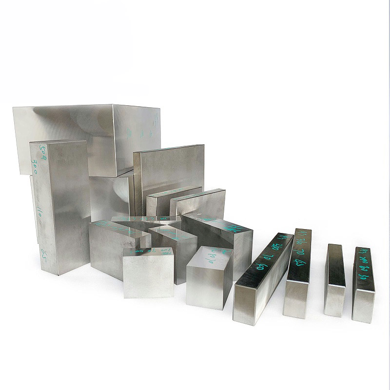
S136 is the mainstream choice for high-gloss phone case molds. After hardening, it reaches HRC 48-52, can be polished to a mirror finish of Ra ≤ 0.03 μm, and has a lifespan of over 1 million shots.
Mold polishing labor rates fall into three tiers (based on 2024 market rates):
- Standard polish (Ra 0.4μm): $12 — $18 / hour
- High-gloss polish (Ra 0.03μm): $30 — $52 / hour
- Ultra-mirror (optical grade) polish: $75+ / hour
The polishing direction must be parallel to the direction of ejection. Polishing against the ejection direction might look better initially, but it will cause drag marks or scratches on the plastic parts during mass production. One company lost over $44,000 on a project because drag marks were only discovered after 50,000 parts had been produced, leading to the entire batch being scrapped.
The polishing path for a high-gloss S136 surface typically involves #3000 grit sandpaper followed by diamond paste with a wool polishing wheel. An orange peel effect can be eliminated with ultrasonic polishing (20-30 kHz), but over-polishing can cause the surface to become hazy.
5. T0, T1, and T2: The Three Acceptance Milestones
Lead times for phone case molds generally fall into three categories: 20-30 days for simple designs, 35-50 days for moderately complex ones, and 55-80 days for precision multi-cavity molds (3-10 days for design, 15-60 for machining, and 3-10 for trials).
But lead time isn’t the most critical factor—the acceptance criteria at the T0, T1, and T2 milestones are. Confusing them leads to problems.
T0 (First Mold Trial)
This stage verifies if the mold structure can produce a part. You should never accept a mold at T0. The T0 trial is only to confirm that the mold can produce a complete part. Appearance, dimensions, and warpage are not yet at the acceptance level. At this stage, mold makers often say, “We can fix it by adjusting the machine parameters.” While parameters like injection speed, pressure, and temperature can be tweaked, they can’t fix fundamental structural issues in the mold, such as gate location, conformal cooling channels, or sequential valve timing.
If the T0 parts show obvious weld lines, excessive warpage, and sink marks, should you believe the “we can fix it in the machine” line? Only partially. If the weld line position can be shifted by adjusting mold temperature or injection speed, it might be fixable. But if the weld line is on a critical high-gloss cosmetic surface, the mold must be modified (by changing the gate location or SVG timing).
T1 (Trial After Mold Revisions)
A full CMI (Critical Manufacturing Inspection) report is required at this stage. This report should cover: ① all critical GD&T dimensions, ② warpage and flatness (≤0.05 mm), and ③ weld line strength (≥70% of the base material, tested per ASTM D638 tensile test).
At the T1 stage, the mold maker should deliver a full dimensional inspection report, at least 5 trial-molded samples, and a record of the process parameters used.
T2 (Final Acceptance / Production Validation)
This involves a continuous production run of 200-500 shots to validate the Cpk (Process Capability Index). Cpk is a statistical measure of production stability. For thin-walled, high-gloss phone cases, a Cpk ≥ 1.33 is the industry benchmark.
At the T2 stage, you need to check for: ① batch-to-batch consistency regarding flow marks, bright spots, and flash; ② consistency of the high-gloss finish; and ③ production cycle time (RHCM cycles are 15-25% longer than conventional molding, which must be factored into the production line’s takt time).
| Milestone | Deliverables | Hard Acceptance Criteria |
|---|---|---|
| T0 | Complete sample parts | Only verifies the mold can produce a part, not for acceptance. |
| T1 | CMI report + 5 sample parts | Warpage ≤0.05 mm, weld line strength ≥70% of base material. |
| T2 | Cpk report (from 200-500 shots) | Cpk ≥ 1.33, stable cycle time. |
The cost of believing the “we can fix it in the machine” myth is high. Structural mold problems can’t be solved by process adjustments. Forcing the mold into production will only lead to mass rejections. If a mold maker tells you a modification will cost $12,000, remember that not doing it could lead to $45,000 in scrapped parts—a classic case of being penny-wise and pound-foolish.
6. What Drawings to Prepare Before Placing an Order
Providing a complete set of drawings upfront can significantly improve the quality and reliability of the mold maker’s proposal. Be sure to include:
- 3D data + 2D drawings (preferably in both STEP and IGS formats)
- Material specifications (PC/PC+GF/PC-ABS) and shrinkage rate
- Appearance requirements (SPI grade, Ra value, texturing specifications)
- Expected annual production volume (to determine the number of cavities)
- Critical dimensions with GD&T (position, flatness, profile)
- Number of trial samples required and acceptance standards
The mold pricing formula is generally:
Total Mold Price = Material Cost (15-30%) + Design Fee (10-15%) + Machining & Profit (30-50%) + Trial Fee (3-5%) + VAT (13%)
For a phone case mold, half the cost is in the steel, and the other half is in the “invisible” details like cooling channels, venting slots, and the parting line. This is what separates a $12,000 quote from a $37,000 one.
If your project is stuck at the decision point between one-shot molding and spray coating, feel free to send your 3D files to moldsteells for a review. We’ll provide an RHCM feasibility report within 3 days, telling you if this route is viable, how much it would cost, and if not, what the limiting factors are.