
Put a game controller shell drawing on the table. Before asking about annual volume or the price of a two-shot mold, mark three areas: the soft-touch zones on the left and right grips, the boundary where the soft and hard materials meet, and the cosmetic surfaces that must not be scuffed, dented, or polished by pressure. The practical differences between two-shot molding and overmolding eventually appear at these three locations.
Two-shot molding completes one mold setup and two injections in one machine and one two-shot mold. The first shot forms the rigid plastic structure, which becomes the substrate. Without leaving the mold, that substrate moves to the second cavity on an internal indexing mechanism, and the soft material is injected. In a separate overmolding process, one mold first produces the rigid part. After the part has cooled and been ejected, an operator or robot places it in a locating fixture inside a second mold, where the soft material is injected. Both routes can produce TPE, or thermoplastic elastomer, grips. The real questions are how the second shot is located, what seals the material boundary, and which record should be checked when a defect appears.
Step 1: Decide How Closely the Two Grip Zones Must Match
Start with a question that can be answered on the drawing: If the left and right soft grips differ in width, or if the palm can feel different step heights along the two seams, is that acceptable? If not, the second-shot locating method may decide the route before production volume does. The two grips form a symmetrical pair. With separate overmolding, any difference between the two fixture references or clamping conditions may become visible sooner than it would on a one-sided housing.
In two-shot molding, a rotary platen or rotating mold core carries the first-shot substrate to the second position inside the mold. The substrate never leaves its locating references, so the soft-grip position mainly follows the repeatability of the mold’s indexing system. Separate overmolding adds a removal, cooling, and fixture-loading cycle. The fixture holds a finished rigid shell, so substrate shrinkage, warpage, and loading variation all become part of the second-shot position error.
Public technical information from the moldmakers Super Ingenuity and Hingtung gives repeatability ranges of about +/-0.01 to 0.05 mm for in-mold indexing and about +/-0.10 to 0.20 mm for fixture loading. These values are the respective suppliers’ published technical references, not universal industry standards, and they cannot replace a dimensional report for the actual project. Their value is that they show which evidence to request. For two-shot molding, inspect the rotary indexing repeatability and the guidance-system measurements. For separate overmolding, inspect how the fixture clamps both grips, which substrate surfaces establish location, and whether the loaded part is measured again.
Two-shot molding is not inherently error-free. Wear in rotary bearings and guide components, combined with the thermal effect of the second shot on the first-shot surface, can gradually shift a soft-grip region that was originally aligned. Separate overmolding is not inherently inaccurate either. If the shell has stable locating surfaces and the fixture preload and incoming-part dimensions remain controlled, it can also produce acceptable grips. The decision branch is straightforward: the tighter the symmetry and boundary tolerances, the more important it is to choose a route backed by evidence of in-mold location. If equipment, tooling cost, or batch size favors separate overmolding, make fixture control and incoming-substrate dimensions explicit tryout conditions.
Step 2: Determine Whether the Shutoff Seals a Hot Part or the Actual Cooled Part
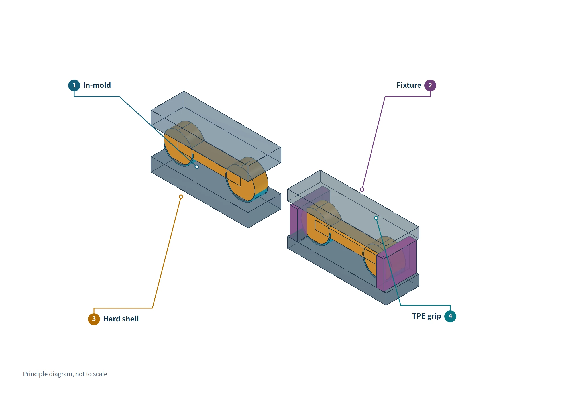
The seam where soft and hard materials meet is the material boundary, and it is the most likely place to show mismatch or flash. Flash is the thin skin created when molten material escapes through a mold gap. Many teams respond by asking only whether the shutoff surface was made correctly. A shutoff surface is the mating steel surface that contacts the rigid substrate and blocks the soft material from flowing beyond the intended boundary. For separate overmolding, one more question matters: Is that shutoff closing against the nominal drawing profile or against the actual cooled shell?
After the first-shot shell leaves its mold, it cools and shrinks and may develop local deformation. When it enters the second mold, the fixture receives a real cooled part. If the second-shot shutoff still closes only to the nominal profile, the material boundary may not seal. Molten soft material will enter the gap first and create flash. The fixture, therefore, uses a controlled preload to hold the cooled part. The handbook 60 Key Points for Two-Shot Mold Design and Injection Molding gives 0.02 to 0.05 mm as a common reference range, but this is not a fixed value that can be copied into every project. Excessive preload can leave a dent or glossy pressure mark on the cosmetic surface.
Two-shot molding presents a different condition. Its second-shot shutoff seals against a first-shot substrate that is still controlled by the mold references. Shutoff design, venting, and indexing accuracy remain necessary, so an integrated process does not eliminate flash. It does, however, remove the variable created by cooling and relocating the substrate. Avient’s public guide, TPE Overmolding Solutions for Engineering Thermoplastics, recommends 0.003 to 0.005 in., or about 0.08 to 0.13 mm, of interference in the shutoff region for a plastic substrate. In other words, the mold surface presses slightly into the rigid plastic to accommodate dimensional variation. A metal substrate has different loading requirements, so this range should not be transferred to metal inserts.
The main issue in separate overmolding is therefore not simply the need for a second mold. The actual substrate dimensions must enter the second-shot design. Measure the grip region and locating references first, then set the fixture preload, shutoff surfaces, and any flash traps. A flash trap is a small groove inside the seam that receives a limited amount of excess material. This procedure does not favor one process. It closes the likely escape path before the tryout.

Step 3: Trace Flash, Mismatch, and Pressure Marks to the First Check
Before freezing the process, rehearse the cost of correcting these defects. Do not wait until production produces heavy edge flash and then rely on manual trimming. Review the defect location, second-shot records, and first-shot dimensions together. The same visible symptom, such as excess material along an edge, can have different causes.
| Observed condition | First area to inspect | How to confirm it |
|---|---|---|
| The left and right soft zones have different widths, or the boundary shifts to one side | For two-shot molding, inspect rotary indexing repeatability and guide components. For separate overmolding, inspect the fixture references and loading sequence. | On samples from the same tryout batch, measure from each soft-grip zone to a rigid-shell datum. Do not judge only by appearance. |
| Flash runs around the material boundary | Inspect shutoff contact, actual substrate dimensions, and preload. | Compare first-shot measurements, fixture preload records, and contact witness marks on the shutoff. Add a flash trap or correct the shutoff if necessary. Do not treat manual trimming as a permanent remedy. |
| The cosmetic surface has glossy marks or dents | Inspect the clamp location and preload used for separate overmolding first. | Overlay the damaged location on the fixture pressure points and determine whether mold steel is pressing directly on the cosmetic surface. |
| A two-shot part also shows flash or peeling | Inspect the shutoff after indexing, venting, and the second-shot process window. | Compare indexing repeatability, the shutoff location, and tryout parameters. Do not assume that two-shot molding cannot produce flash. |
When we at moldsteells review this type of Molde de inyección de plástico proposal, we place the first-shot dimensional report, second-shot indexing or fixture record, tryout parts, and defect photographs on the same table. This is not a proprietary moldsteells procedure. Any supplier’s proposal should withstand the same review. A plan has been tested in an executable way only when each defect location can be traced back to a specific locating datum, loading step, or shutoff surface.
Use Three Records to Choose the Route, Not One Quotation
If the controller shell demands close left-right symmetry, a narrow material boundary, and cosmetic surfaces free of pressure marks, evaluate two-shot molding first. The reason is not that two-shot molding is more advanced. The supplier must be able to submit records covering rotary indexing repeatability, guide accuracy, and tryout dimensions. If tooling budget, available equipment, or batch size is the stronger constraint, separate overmolding can be a reasonable choice. Its fixture location, measured substrate dimensions, preload, and shutoff surfaces must be verifiable tryout conditions rather than verbal assurances.
For either route, place at least three items side by side before production: the first-shot critical-dimension report, the second-shot indexing or fixture settings, and tryout samples marked with defect locations. During the design-for-manufacturability review, confirm the shutoff, vent locations, and protection of cosmetic surfaces. Test the actual material combination with peel specimens. Production volume affects the tooling and equipment investment, but evaluate it after these structural and verification requirements. That order helps prevent a controller shell from passing a few samples and then requiring repeated mold corrections during production.