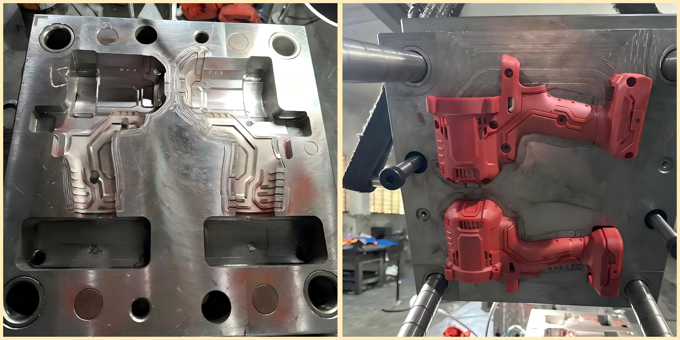
For a 1.5 m drop test, don’t rush to accept a mold factory’s blanket promise—this figure is not a national standard value.
The Chinese national standard uses 1 m, three drops, and a concrete surface as the pass criterion. From IEC 60745-1, the general safety requirements for hand-held electric tools, to the newer IEC 62841-1, that baseline has not changed. The 1.5 m requirement is a stricter internal control target set by brand owners and lithium-battery tool customers. It is 50% tougher than the safety standard. A customer throws out one line—”the housing must pass a 1.5 m drop test”—and all you have is a 3D drawing. Which resin should you choose? How should the structure be designed? Which numbers matter most at the T0 trial? Many buyers and engineers are not confident about those decisions.
This article breaks the issue down from the mold structure design side: where the 1.5 m requirement comes from, what material grade to pick, what structural rules to follow, what the mold side must do to support the design, and finally how to judge at T0 whether the part is likely to pass. After reading it, you will know which parameters must be locked in before mold build starts—instead of guessing only after the sample cracks in a drop test.
Where the 1.5 m Requirement Comes From
The 1.5 m requirement was not picked at random. It comes from three stacked layers of tougher requirements. Lithium-battery tools must pass 3C certification for the battery under the GB 31241 system, and the mechanical strength item already requires a 1.5 m six-face drop test. In government procurement tenders for power tools, housing material requirements are often spelled out in black and white as “the bare tool must withstand a 1.5 m drop impact.” Then brand owners add their own internal standards, and most lithium-battery tools are judged against 1.5 m. Put those three together, and 1.5 m becomes the default inspection line in this business.
What is the baseline safety requirement? For general hand-held tools, it is a 1 m drop, three times, at the three most unfavorable positions, onto a concrete surface. Clause 20.3 of GB 3883.7-2012, the special requirements for hammer tools, states it clearly: tools weighing no more than 10 kg must withstand three drops from a height of 1 m onto a concrete surface. If a customer inspects at 1.5 m, that means adding 50% more impact energy on top of the safety baseline.
This point must be made clear before tooling starts. If a supplier uses “the national standard doesn’t require it” to push back on 1.5 m, that is a category switch, not a valid technical argument. If you plan to inspect at 1.5 m, do not expect the mold factory to design to that level automatically. Put the exact standard, height, and number of drops into the contract. That matters more than any verbal promise.
How to Choose Housing Material
If the material is wrong, even a well-designed structure will not save the part. Material choice sets the lower limit for drop performance.
For professional-grade angle grinders and rotary hammers, the housing is usually based on PA66+GF30, or glass-fiber-reinforced nylon 66. The reason is simple: about 120 °C heat resistance, high stiffness, and good dimensional stability. It can handle the temperature rise around the motor chamber. But one common misunderstanding needs to be cleared up: glass-filled material is not automatically better at surviving drops. Glass fiber improves stiffness and heat resistance. It actually lowers impact toughness compared with PC/ABS. When glass-filled nylon performs well in drop tests, the structure is doing most of the work—not the resin alone. In pure drop-impact toughness, PC/ABS is one level stronger.
| Housing Material | Heat Resistance | Drop Impact Resistance | Low-Temperature Performance | Cost (USD/kg, 2026 market) | Typical Application |
|---|---|---|---|---|---|
| PA66+GF30 | About 120 °C | Medium (notched impact about 10-15 kJ/m²) | Good, usable at low temperature | 4.15-5.19 | Professional grade, where heat resistance and stiffness come first |
| PC/ABS alloy | About 125 °C | Strong (typically about 25-45 kJ/m²) | Clear decline at about -10 °C | 3.70-4.44 | Mainstream all-around choice, where drop resistance comes first |
| ABS | About 70 °C | Medium to fairly strong | Becomes brittle at low temperature | 1.78-2.22 | Entry-level household tools |
(The impact strength ranges above are typical reference values. They vary by grade, but the trend is reliable.)
PC/ABS is the most widely used resin for power tool housings. PC provides impact resistance, and ABS makes molding easier. Heat resistance can exceed 120 °C. Its weak point is low temperature. At around -10 °C, impact toughness drops noticeably. For tools exported to Northern Europe or Russia, a winter drop can make PC/ABS crack in a brittle way. If low-temperature toughness matters, PA66+GF or a cold-resistant PC/ABS grade is a hard requirement, not a matter of preference.
Changing material is also the most expensive correction path. Abs costs only around a couple of dollars per kilogram, while PA66+GF30 is around $4 to $5 per kilogram. Moving from entry-level to professional grade can add several dollars to the cost of each part. So the right order is to fix the structure first. Rib layout, radii, and wall thickness can often be improved through mold modification at almost no added part cost. If the part still fails after that, then discuss material change. Switching resin too early means asking material to solve a problem the structure should have handled.
What to Watch in Structural Design
Most drop-test cracks start at the corners. That is where the full impact energy hits the latch root and the rib intersection. So corner design and corner radius matter more than large flat surfaces. Ranked by frequency, the four main failure modes are corner cracking during drops, latch breakage, cracking at weld lines, and cracking at the motor mount or handle root. If you control the first two, half the drop problems are already gone.
Ribs are the main structural feature for drop resistance and stiffness. Rib thickness should be 0.5-0.7 times the nominal wall thickness. Rib height should not exceed 3 times the wall thickness. The root radius should be at least 0.5 times the wall thickness. Rib spacing should be more than 2 times wall thickness. Go beyond those numbers, and you are not adding strength. You are creating sink marks and crack initiators. If the cosmetic surface must stay free of sink, rib thickness needs to be limited to about 0.3 times wall thickness.
Wall thickness must stay uniform. 2.5-4 mm is the typical range for professional-grade housings. Sharp thickness changes are the worst case. Drop impact will tear the part open right at the transition. If a transition is unavoidable, use a gradual 3:1 taper instead of a step. A thicker wall is not always stronger. Cooling time rises almost with the square of wall thickness, so thicker walls cost more and are more likely to create sink.
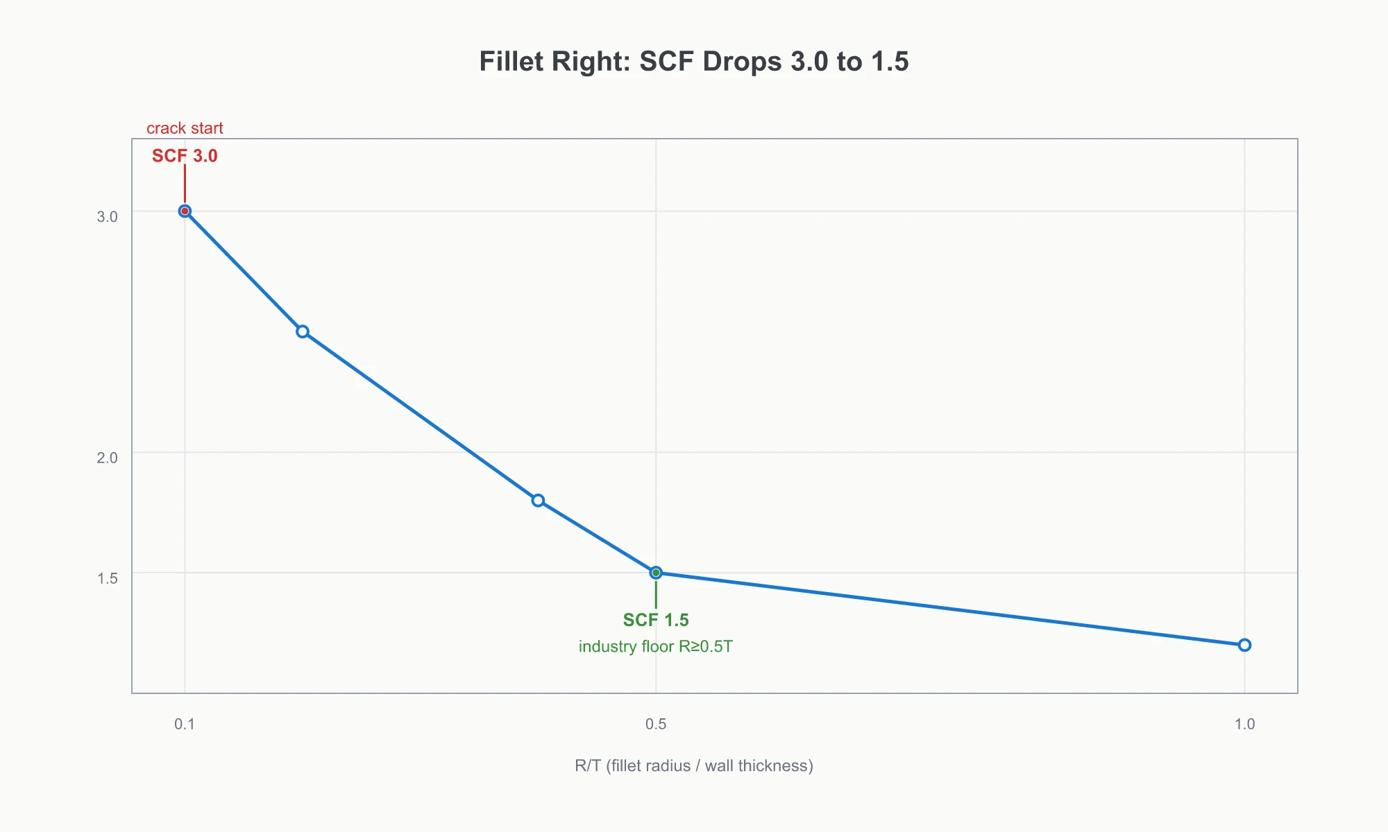
Sharp corners are crack starters because injection-molded parts are notch sensitive. When the corner radius is only one-tenth of wall thickness, the stress concentration factor can reach 3. When the radius reaches at least half the wall thickness, it can be reduced to about 1.5. That is the industry’s minimum line. Three locations must have proper radii: latch roots, rib intersections, and wall-thickness transitions.
Latches are the single most common drop failure point. The root radius should be no less than half the latch thickness. Do not create a cross-shaped intersection between a latch and a rib. That intersection becomes a stress concentration point during a drop. For cantilever latches, thicken the root gradually. Do not use a sharp 90-degree transition. It is often better to make the latch slightly smaller at first and leave tuning room for mold changes. Latches are one of the most frequently revised features in drop-resistant housing projects. If you make them too aggressive on the first shot, they become harder to fine-tune later.
When a corner takes the hit, the full impact load goes straight into the latch root.
What the Mold Side Must Do
Gate location determines weld-line location. In many factories, the gate is simply called the sprue or gate point. The weld line forms where two melt fronts meet in the cavity. Bond strength there is weaker, and it is a common crack location in drop tests. Three rules matter here: place the gate at the thicker section so resin flows from thick to thin; keep weld lines away from load-bearing areas such as latches, handle roots, and corners; and provide a sufficient cold slug well so cold material does not enter the cavity. Mold flow analysis exists for exactly this reason. Before tooling starts, calculate where the weld line will land and move it out of the load zone. It is far cheaper to fix this in the mold than in the part design.
Ejector whitening is hidden internal stress inside the part. If draft is not enough, ejection force goes up. Then the part shows ejector whitening. That means internal stress has been trapped inside the molding, and the part may crack from that location in a drop test. Draft is not just about appearance. Smooth surfaces need at least a 0.5° draft. Textured surfaces should go above 2°. Heavy texture should go above 3°. Tall ribs require an extra 1° of draft. Ejector pins should be laid out in a dispersed and balanced pattern. Do not let one local point take the full force. Internal undercut features such as latches should reserve space for lifters or angle pins. Do not force an undercut into a straight-pull design.
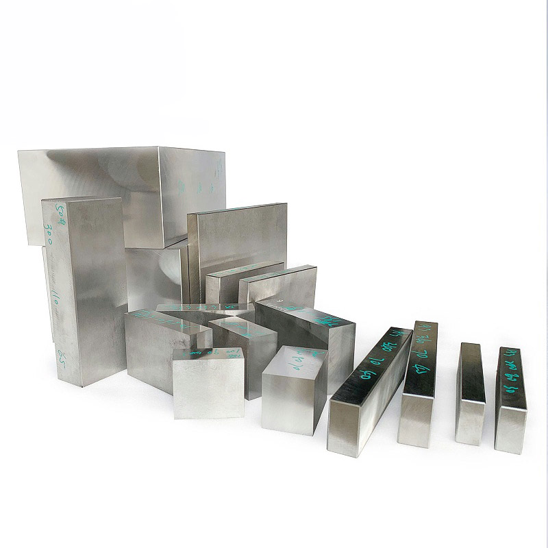
Choose mold steel by working condition, not by price escalation. For housing molds, pre-hardened 718H or NAK80 is usually enough. They can support mold life in the hundreds of thousands of cycles and still provide the needed polish level. If cost must be controlled, P20 at HRC 28-32 can work. S136 is usually reserved for transparent parts. Housing molds are not extreme wear applications, so there is no need to jump to H13 or DC53. Before launching an Injection Mold project, put these requirements into the mold specification sheet. That will save one full iteration cycle compared with arguing during trial runs.
How to Predict Pass or Fail at T0
A capable mold factory starts drop screening at T0—the first machine trial and first sample run. First test at 1 m, then move to 1.5 m to check margin. The crack location will tell you what is wrong: bad rib design, stress introduced by gate location, or internal stress caused by ejection damage. The most common T0 crack locations are latch roots and corners. That does not mean the mold is scrap. It means the tool should move into T1 correction. If you wait until mass production to run the drop test, even a small mold change can turn into a major disruption.
At the T0 stage, three checks on the mold side are enough to make an early drop-performance judgment:
| Check Item | How to Check | Cost of Missing It |
|---|---|---|
| Weld-line landing position | Review the mold-flow report and confirm whether it falls at the latch, handle root, or corner | The part cracks from the weld line during the drop test |
| Whether corner radii are sufficient | Check that R ≥ 0.5T at latch roots, rib intersections, and wall-thickness transitions | Stress concentration and corner cracking |
| Drop screening | Start at 1 m for 3 drops, then test 1.5 m to assess margin | The issue appears only at final inspection, and mold correction comes too late |
Customers typically inspect against two points: no through-cracks and normal startup after the drop. For live parts and the housing, insulation resistance is typically required to stay at or above 2 MΩ. Deep scratches that expose the substrate can also trigger rejection. That is why customers often record the full test and sometimes bring a benchtop hardness tester. There are only three practical ways to handle disputes: define the standard, height, and number of drops in the contract before production; record the drop process on video as evidence; and prepare three sets of samples.
FAQ
Is a 1.5 m drop test required by the national standard?
No. Under the GB 3883 system and IEC 60745/62841, the general drop baseline for handheld tools is 1 m with three drops. The 1.5 m requirement is a stricter condition set by brand owners, lithium-battery tool customers, and procurement tenders. It is 50% tougher than the safety baseline. When a supplier says “the national standard doesn’t require it,” they are using the minimum line as if it were the target line.
Is glass-filled material more drop-resistant?
No. PA66+GF30 improves stiffness and heat resistance, but its impact toughness is lower than PC/ABS. Glass-filled nylon survives drops mainly because of structural design, not because the material itself is inherently tougher. If pure drop toughness is the priority, choose PC/ABS. If heat resistance and stiffness matter more, pick glass-filled nylon. Each solves a different problem.
Does a thicker housing wall always improve drop resistance?
No. Uniform wall thickness comes first. The typical professional-grade range is 2.5-4 mm. Sudden thickness changes become stress concentration points, and the part tears open there during a drop. Use a 3:1 gradual transition instead of a step.
If the T0 sample cracks in a drop test, is the mold scrap?
No. T0 exists to find problems. The crack location points to the cause. Cracks at latch roots and corners mean stress concentration. Cracks at weld lines mean a gate-related issue. Cracks at ejector whitening points mean the draft is insufficient. The fix is to adjust ribs, move the gate, or add draft, then verify again after T1 correction.
What a 1.5 m Requirement Reveals About How a Mold Factory Works
The answer to a 1.5 m drop test is not the drop itself. It is in the design work done before tooling starts. Structure is the first line of defense, material is second, mold support is third, and T0 is the stage where that defense gets verified. Reverse that order, and the cost doubles. Changing material first, modifying structure second, and only then checking the mold is the most expensive path. At the root of it, this is a design-discipline issue: before tooling starts, the 1.5 m requirement must be treated as a design problem that is 50% tougher than the national baseline.
moldsteells works in Plastic Injection Molding, and molds for power tool housings and structural parts are one of its main businesses. The team tracks these checkpoints with customers from T0 onward—weld-line landing position, radius parameters, and early drop-screening results. Those judgments show up in the details of how a mold factory works, not in the quotation sheet.
Bring these checklists to the DFM review meeting and go through them line by line with the mold factory. The supplier that can match them is the one most likely to help the housing pass the 1.5 m drop test.