Few repair situations are more frustrating in a Mirror Finish Injection Mold than finding more pits and more obvious orange peel after fine polishing. If every such defect is treated as unfinished polishing, added pressure, longer polishing time, or a finer abrasive, it may alter the original evidence and leave the investigation with no reliable starting point.
The first question is not how much longer to polish. It is whether the defect is on the steel surface, on the molded part, or on both. Once the affected object is confirmed, check the steel heat and heat-treatment records, the areas that were actually machined by electrical discharge machining (EDM), and the surface changes left by each polishing stage. Only then should controlled molding trials be used to isolate molding-related effects.
This type of repair should not be handed to the polishing operator alone. When we at moldsteells handle such a case, the moldmaking, EDM, polishing, trial-molding, and quality teams work with the same set of reference numbers. The moldmaker marks the defect coordinates and actual EDM areas. The polishing operator records surface changes before and after each stage. The trial-molding and quality teams preserve the settings, photographs, and samples produced under the same conditions. Once these records align from one step to the next, the team can decide which process to investigate next and where work must stop.
Should You Inspect the Cavity or the Molded Part First?
Stop polishing first and preserve the existing condition. Before repairing the cavity again, fix the light source, incident angle, camera distance, and magnification, then take overview, close-up, and oblique-light photographs. Mark coordinates or zone numbers against mold datums. Photograph molded parts with the same viewing surface, orientation, and lighting while recording the resin lot and the shot number or sampling sequence. Without these baseline photographs, a later appearance change cannot reliably show whether the defect disappeared, shifted position, or merely looks different because the photography changed.
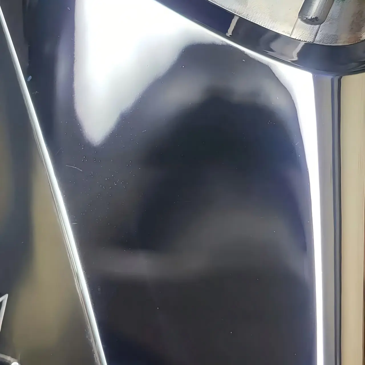
Next, separate two terms that are often confused. Orange peel on a steel surface means fine waves or localized unevenness visible after polishing. It may be associated with overpolishing, localized loading, or material structure. A molded plastic part can show an orange-peel-like appearance for entirely different reasons, including filling, packing, temperature, venting, or melt uniformity. The two may look similar to the naked eye, but the object requiring correction is different. Pitting must also be classified by its object: cavities in the steel surface, bright or dark spots on a molded part, and small gas-related pits cannot be grouped together simply because people use the same name for them.
Begin with the physical evidence. Clean the cavity without changing its surface condition, then use oblique lighting and magnification to confirm whether the steel truly contains pits or waves. Place defective and acceptable molded parts side by side and compare the defect boundary, orientation, density, and change from shot to shot. If the molded part is defective but the corresponding steel surface shows no abnormality, do not touch the cavity yet. If a clear feature is already visible on the steel, do not immediately attribute every molded-part appearance issue to the steel. First determine whether that feature is reproduced consistently on the part.
| Observation | What it currently indicates | What it does not yet prove |
|---|---|---|
| Pits or waves are visible on the cavity steel | The source of the cavity-surface defect requires further investigation | The shape alone cannot assign responsibility to the steel, EDM, or polishing |
| An appearance difference repeatedly occurs in a fixed area of the molded part | The defect has a stable spatial relationship | It does not prove that the cavity is damaged |
| The molded-part appearance changes with molding conditions | Molding conditions contribute to defect formation | It does not exclude an influence from the cavity surface |
| Cavity topography matches a replicated feature on the molded part | The likelihood of cavity influence increases | Resin variation, contamination, and observation error still need to be excluded |
Same-Location Recurrence Does Not Assign Responsibility
“It appears in the same place on every shot” is useful because it narrows the search from the entire mold to one local area. It is an investigative clue, not proof of cavity damage. A fixed location can result from the cavity surface, but it can also result from a fixed wall-thickness transition, gate direction, weld region, local mold temperature, or venting condition. These factors do not move randomly between shots and can repeatedly produce gloss differences, waves, or pit-like marks in one area of the molded part.
Judge the replication relationship, not just the coordinates. If a cavity pit is being replicated, the corresponding feature on the molded part should have a comparable orientation, outline, and detail. A molding-related appearance defect often changes in intensity or boundary when injection speed, temperature, the velocity-to-pressure transfer point, or cooling conditions change. The two causes may also overlap: the cavity may already have slight topography, while a particular process window makes it more visible. In that situation, expecting one molding trial to identify a single responsible party is premature.
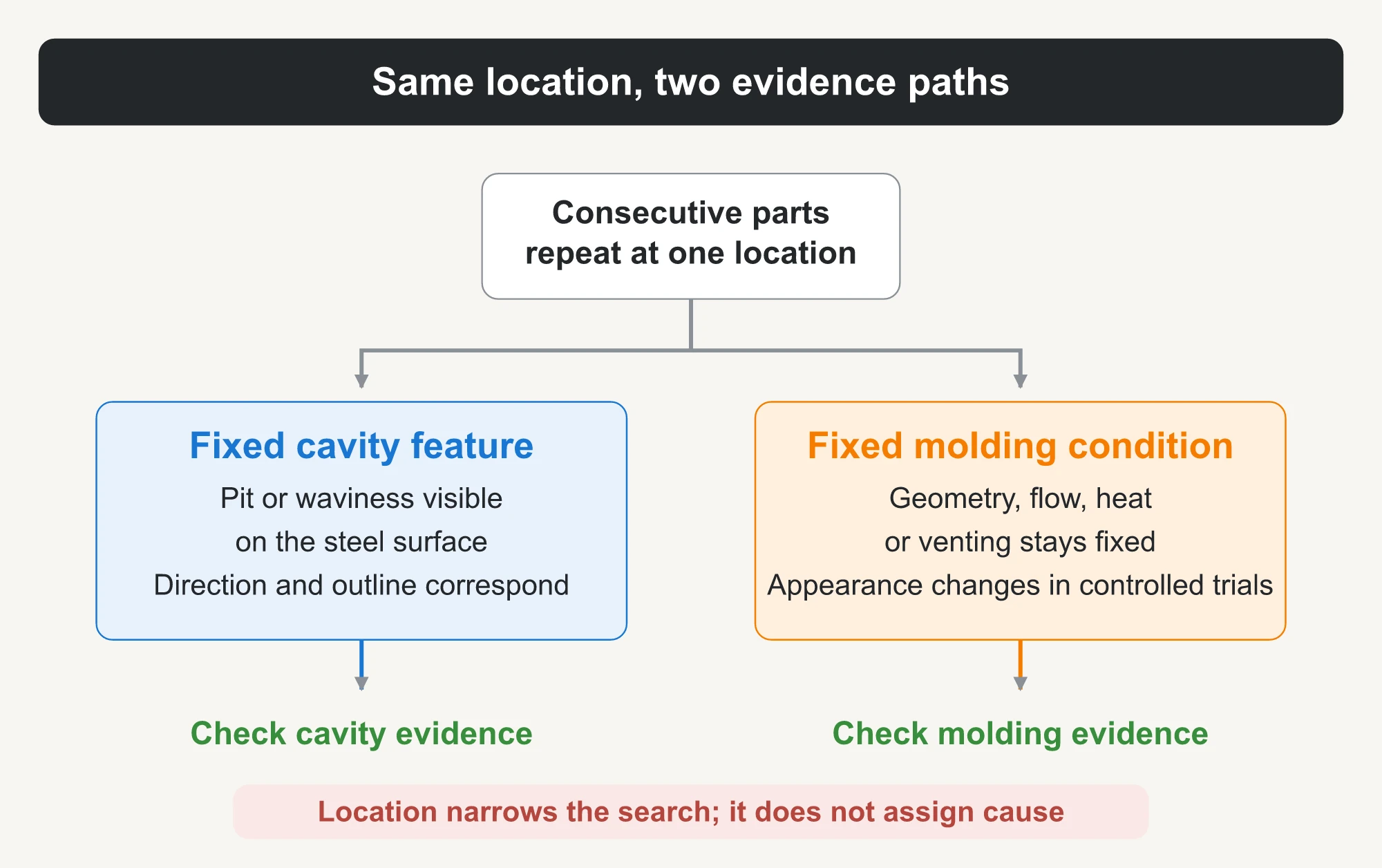
A safer approach is to preserve the original baseline and begin with checks that do not remove steel. Change the inspection lighting, verify the defect coordinates on the cavity, compare consecutive molded parts, and determine whether controlled molding changes produce repeatable changes in the defect. Move the repair focus to the steel only when the cavity itself has identifiable topography and the replication relationship on the molded part also matches. If the evidence goes no further than “the position is the same,” polishing the steel removes the surface that is hardest to restore before the cause has been established.
Use Steel Records to Trace Upstream Causes
Do not begin a real investigation with grade-marketing claims. Begin with the actual records for the insert. At minimum, verify the heat number or material certificate, stock orientation, the Heat Treatment batch, hardness records, repair welding, and any history of localized heating. Also check whether steel from the same heat showed pitting or orange peel in comparable machined areas. Mark missing records as pending; do not fill the gaps with assumptions.
Mirror polishing can bring internal material differences to the surface. If new fine pits appear during fine polishing, investigate heterogeneous particles that may previously have been inconspicuous within the steel. Such non-matrix particles are inclusions. Softer inclusions may be pulled out first and leave small cavities. With harder heterogeneous inclusions, the surrounding matrix may be polished down first and the particles may later detach, also leaving pinhole-like depressions. When microstructure or hardness is uneven, different areas are removed at different rates, so fine undulations can emerge during fine polishing. These mechanisms explain why little may be visible during coarse finishing while more pits appear at the fine-polishing stage. The appearance of pits alone, however, does not prove that the steel contains inclusions.
If hardness, heat-treatment, or repair-welding records provide a material-side lead, plan verification around that evidence. For example, compare hardness first in a location that will not affect cavity function. If microstructure or inclusions genuinely need to be evaluated, use a qualified laboratory for metallographic examination or material verification under controlled sampling conditions. Sampling location, orientation, and specimen preparation all affect the result; one unverified local reading cannot represent the entire steel block. Whether ultrasonic testing was performed and who was responsible for heat treatment must be determined from project records. In the absence of records, neither should be presented as a fact.
Record the steel investigation in specific terms: which records agree, which are missing, which observations support further material investigation, and which observations do not fit a material explanation. A note that merely says “the steel may be poor” cannot determine whether metallographic examination or material verification is needed, nor can it tell the polishing operator where the next stage must stop.
Map the Areas That Were Actually EDM-Machined
Investigate EDM only where EDM was actually performed. Use process drawings, programs, EDM copper-electrode identifiers, machine records, and visible machining evidence to map those areas. Then compare the locations of pits or orange peel with each EDM zone. If the problem area was never EDM-machined, skip this layer and investigate cutting, grinding, material, polishing, and molding instead. The presence of EDM somewhere on the mold does not mean the entire cavity was affected by it.
The high temperature of electrical discharge machining melts the steel surface. Rapid cooling resolidifies this material into a recast layer, also called a “white layer.” Beneath it lies unmelted material affected by heat, known as the heat-affected zone (HAZ). Recast layer continuity, defects, and depth, as well as the condition of the HAZ, vary with the steel, discharge energy, machining stability, and flushing conditions. One fixed layer thickness or universal removal allowance cannot be applied to every material. Before mirror finishing, determine which EDM operation produced the area; the condition of the finish-EDM pass; whether subsequent grinding or polishing removed the abnormal surface layer adequately; and whether polishing direction has concealed marks from an earlier stage.
Compare the problem area with a non-EDM area on the same insert and with an acceptable area produced by the same process. If the defect boundary follows the EDM zone and corresponds with recorded discharge abnormalities, suspicion of an EDM-related upstream cause increases. If the defect crosses the boundary with continuous morphology, reassess material structure, subsequent grinding, or contamination. A matching boundary is still supporting evidence only. Records, surface observations, and controlled before-and-after repair changes must corroborate one another.
Stop When Fine Polishing Makes the Surface Worse
Fine polishing is not a universal remedy for upstream process problems. It can reduce fine marks on a surface that is already flat and uniform, but it cannot refill cavities left by detached particles. Nor can it automatically remove a residual altered layer, deeper scratches from a previous stage, or differences in material structure. Softer tools and finer media make the surface brighter, which can make previously inconspicuous pinholes and local undulations easier to see. This is one common explanation for “more pits after more polishing”: not every newly visible pit was created during that polishing step; some earlier defects were merely exposed.
Overpolishing can further damage the steel topography. Excessive localized pressure, prolonged dwell, or an unsuitable tool condition can produce uneven material removal and gradually create orange-peel-like waves. If the boundary of the same small area expands after a fine-polishing pass, the waviness increases, or details become rounded, stop immediately. Save photographs and record the tool and polishing medium in use. Then decide whether to return to the preceding abrasive stage that still has enough cutting action to correct the surface. The appropriate stage depends on the observed topography and upstream records; do not prescribe a universal grit, duration, or stock-removal amount in advance.
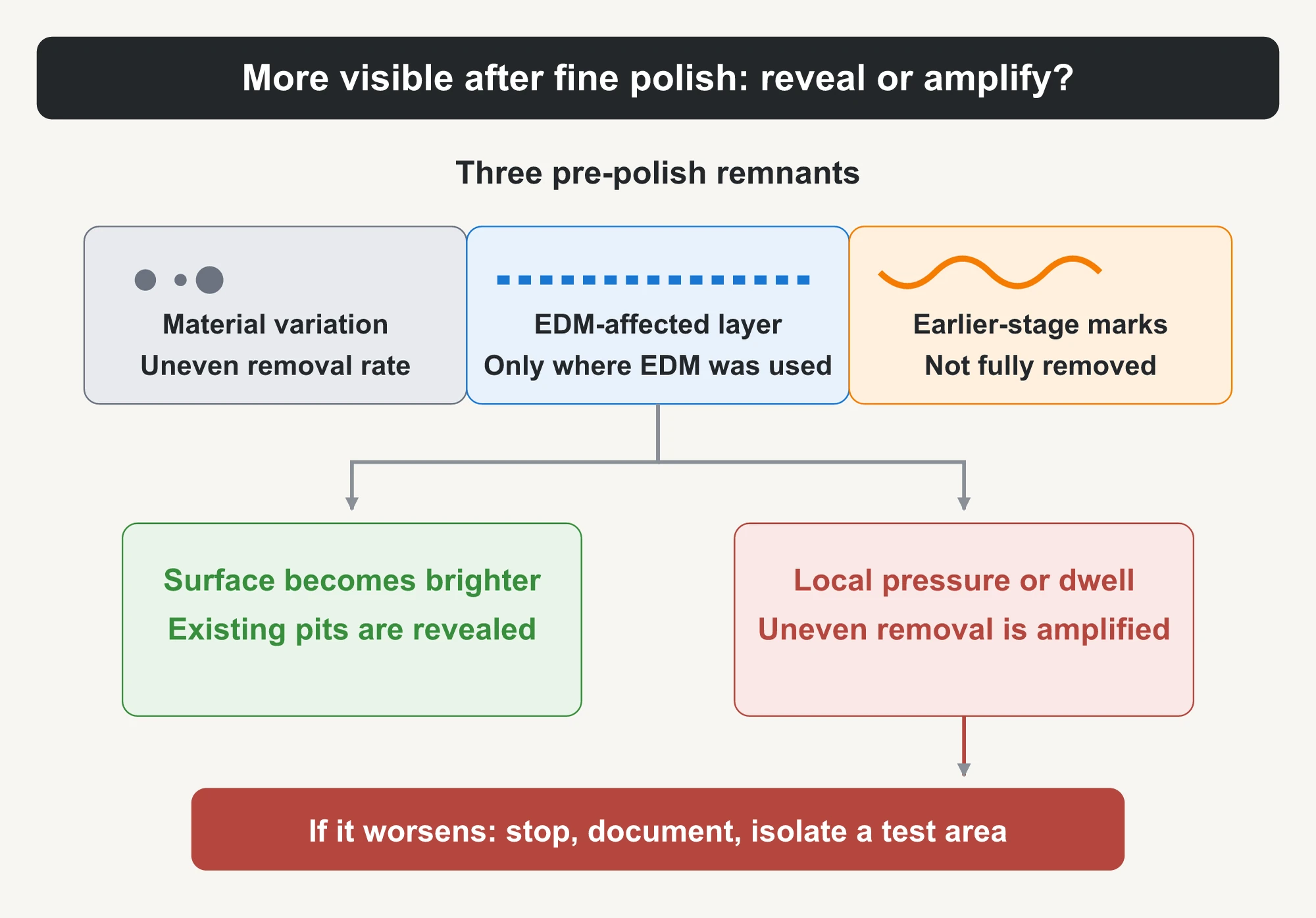
When reworking the area, begin with a small test zone instead of repairing the entire surface. Record tools, media, and cleaning conditions separately to prevent coarse particles from an earlier stage from contaminating fine polishing. In each cycle, remove only enough material to reveal the direction of change, then stop and compare under identical lighting. Determine whether the number of pits increased, decreased, or merely became clearer; whether the orange-peel boundary expanded; and whether geometric edges became rounded. If the small test zone continues to deteriorate, suspend polishing and reopen the material and EDM investigations.
How to Run Controlled Molding Comparisons
After inspecting the steel surface, use controlled trial molding to isolate molding effects on the plastic part. First lock the baseline: use the same mold, cavity, resin lot, and drying condition, and keep the machine, mold-temperature system, cooling connections, sampling time, and inspection lighting consistent. If the baseline itself is drifting, a supposed one-variable comparison has no reliable meaning.
Start with one condition most closely related to the defect location and adjust it in small steps. Candidates include the injection-speed profile, melt temperature, mold-surface temperature, velocity-to-pressure transfer, and holding pressure. Once the baseline is stable, change one setpoint at a time while keeping all other controllable conditions unchanged. This is a single-variable verification. The report must also record actual process outputs because these conditions interact. Changing injection speed can also change fill time, peak pressure, and shear heating. Changing melt temperature changes viscosity and pressure response. Reading only the settings screen can make an interacting response look like a single cause.
| Comparison | Baseline that must remain unchanged | Actual response to record | How to interpret the result |
|---|---|---|---|
| Injection-speed profile | Material, mold temperature, packing, and cooling | Fill time, pressure trend, and defect boundary | If appearance changes repeatably with speed, flow is involved, but cavity replication is not automatically excluded |
| Melt temperature | Speed settings, resin condition, and mold temperature | Actual melt temperature or available process records, plus pressure response | If defect intensity changes consistently and repeatably across trials, continue investigating melt uniformity and filling; use viscosity or pressure only as explanatory evidence |
| Mold-surface temperature | Cooling connections, flow condition, and all other settings | Measured temperature and stabilization time | If local gloss changes with temperature, recheck heat transfer and cooling consistency in that area |
| Velocity-to-pressure transfer or holding-pressure level | Filling stage and cooling time | Part weight, pressure response, and local appearance | If weight and appearance change together, packing is more likely to contribute |
If several conditions are strongly coupled, a one-variable test can indicate only a general direction and should not be forced into a single-cause conclusion. Within the engineering limits of the process, a small combined experiment may then be used. Run two or three key conditions in predetermined combinations and collect enough stable parts from each condition. The design must reflect the actual machine, resin, and mold state; a generic parameter table cannot be applied directly.
Which Baselines Must Be Locked for Verification?
Verification after repair or process adjustment must answer three questions: what changed, whether the other conditions remained comparable, and whether the change can be repeated. For the cavity, lock the observation coordinates, cleaning method, light angle, magnification, and treated area for each cycle. For polishing, record the tool, medium, operator, duration, and direction, but do not treat duration itself as an acceptance criterion. For molding trials, lock the resin lot and condition, machine, cavity, mold temperature, and cooling connections, and retain both setpoints and available actual process data.
For every revision, retain at least one set of standardized cavity photographs and the corresponding molded parts. The reference number should retrieve the related EDM, polishing, trial-molding, and quality records. Define the evaluation method before testing: compare the number and distribution of pits, the boundary and direction of orange peel, changes in molded-part gloss, and whether cavity-surface features still replicate at the corresponding location on the part. Also confirm that the repair has not damaged edges, dimensions, or other functional surfaces. Without predetermined evaluation criteria, a surface that merely “looks a little brighter” can easily be mistaken for a conclusion.
Stop further trial and error in any of three situations: the same polishing or molding operation does not produce a repeatable appearance, baseline drift makes comparison impossible, or the defect expands and geometric surfaces begin to deteriorate. Restore comparable conditions in the first two cases. In the third, immediately compare the current condition with the pre-repair records and reconsider whether material verification, upstream EDM correction, or a change to the polishing process is required.
To resolve pitting and orange peel on a mirror surface, preserve the original topography first, then narrow the investigation by separating steel-surface evidence, molded-part evidence, and actual machining areas. Keep comparable records for every repair step and molding trial. Even if the defect has not yet been eliminated, those records will show where the next investigation should begin.