
When the material grade, supply condition, or sheet thickness changes, the original blanking clearance cannot be carried over unchanged. First confirm whether the drawing defines clearance per side or as a total. Then use the material and measured thickness to set a first trial window. During the trial, keep each sample tied to the feed direction and read the four fracture zones, burr distribution, dimensions, and edge condition. This helps separate a whole clearance adjustment from a problem with alignment, guidance, or edge condition.
The percentages below establish a starting window only. They do not replace the drawing, process sheet, or validation with the same material batch. Fine blanking also needs its process data; do not apply an ordinary blanking table by simply scaling the numbers down.
Define the Clearance Convention First
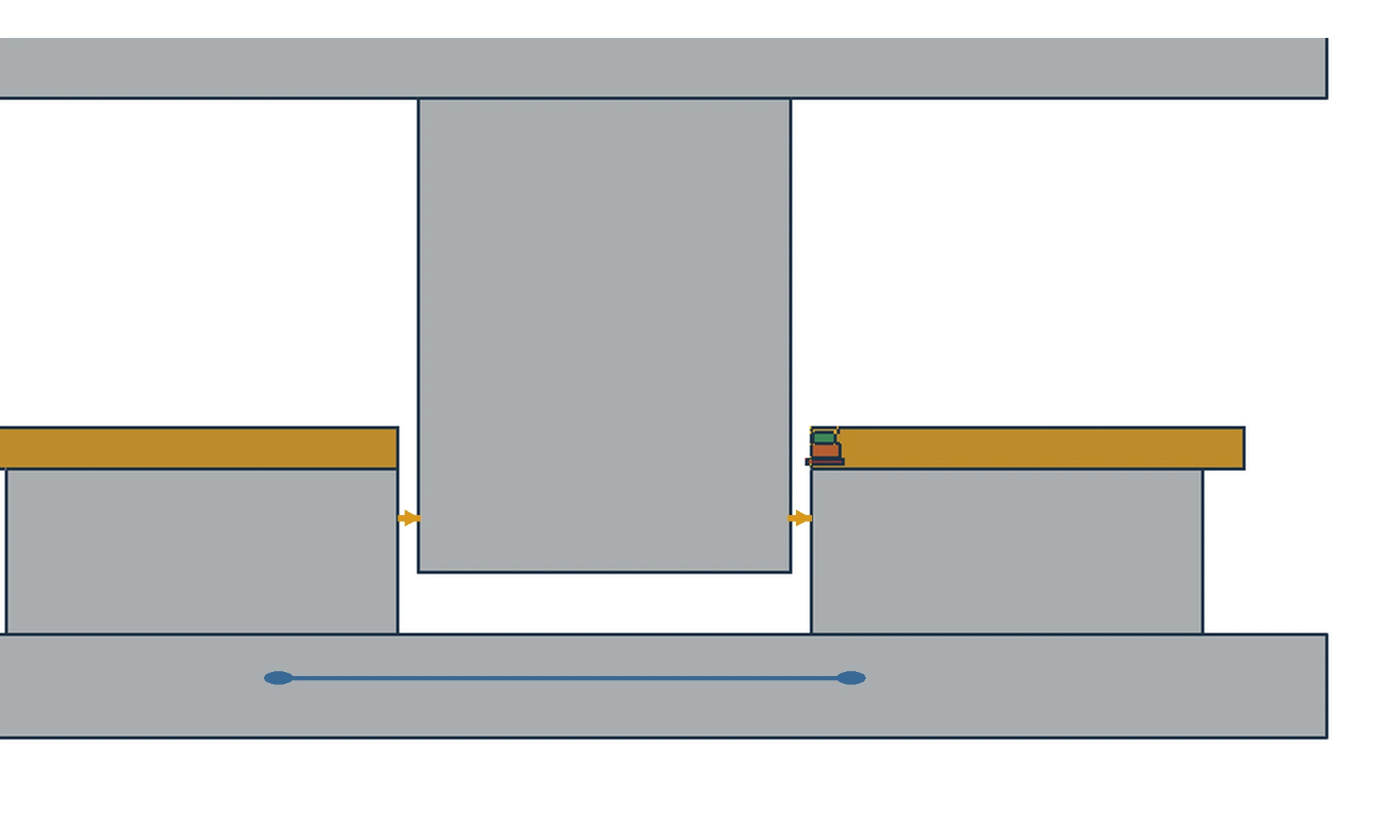
A drawing that says “10% of sheet thickness” still does not tell you the rework dimension. Let it c be the one-side clearance, the distance from one punch cutting edge to the corresponding die cutting edge. Let it C be the total clearance across both sides:
C = c_left + c_right
When centered and equal on both sides: C = 2c
When a table gives a per-side percentage k: c = k × t
Here is an arithmetic check only: with sheet thickness t = 2.00 mm and a process sheet that confirms k = 10% per side, c = 0.20 mm and total clearance C = 0.40 mm. If the process sheet means 10% as the total, C = 0.20 mm and each side is only 0.10 mm. The readings differ by a factor of two. This is not a recommended setting; it shows why the convention must be aligned first.
Write four items on the trial sheet before setup: material grade and supply condition, measured sheet thickness, ordinary or fine blanking, and whether the percentage is per side or total. If one item is missing, complete the record before grinding the punch or die.
The decision is straightforward: when the convention and blanking objective are clear, move to the starting window. If the drawing is ambiguous or different documents use different conventions, return to the drawing, process sheet, and design confirmation first.
Adjust the Starting Window for Material and Thickness
When the material changes, the first change is the starting point of the window. Multiplying the old percentage by a simple ratio is not enough. A public MISUMI technical table can serve as a first reference for ordinary blanking:
| Material category | Ordinary blanking reference relative to thickness | Use boundary |
|---|---|---|
| Soft steel | Approx. 6–10% | Starting range only; confirm the table convention |
| Hard steel | Approx. 9–15% | Re-trial when strength, ductility or measured thickness changes |
| Stainless steel | Approx. 7–12% | Do not copy across grades without validation |
These are relative-thickness reference windows, not final machining values. Material strength, ductility, thickness, profile geometry, edge condition, and tool-life targets can all change the result. High-strength material, especially, should not be reduced to the rule “higher strength always means more clearance.” Public tables also do not decide whether a percentage is per side or total, so use the formula above to record the convention.
Use this first-window branch: for ordinary blanking with material condition and thickness inside the table boundary, use the listed range as a starting point. For fine blanking, return to the relevant fine-blanking process table and quality target instead of forcing an ordinary-blanking value into the job. If the grade, hardness, or quality target lies outside the table boundary, mark the window for targeted validation rather than presenting it as a universal answer. Record round holes, corners, and narrow profiles as notes on the trial sheet; without project data, do not declare that one profile must always take the high or low end.
Read the Four Fracture Zones First
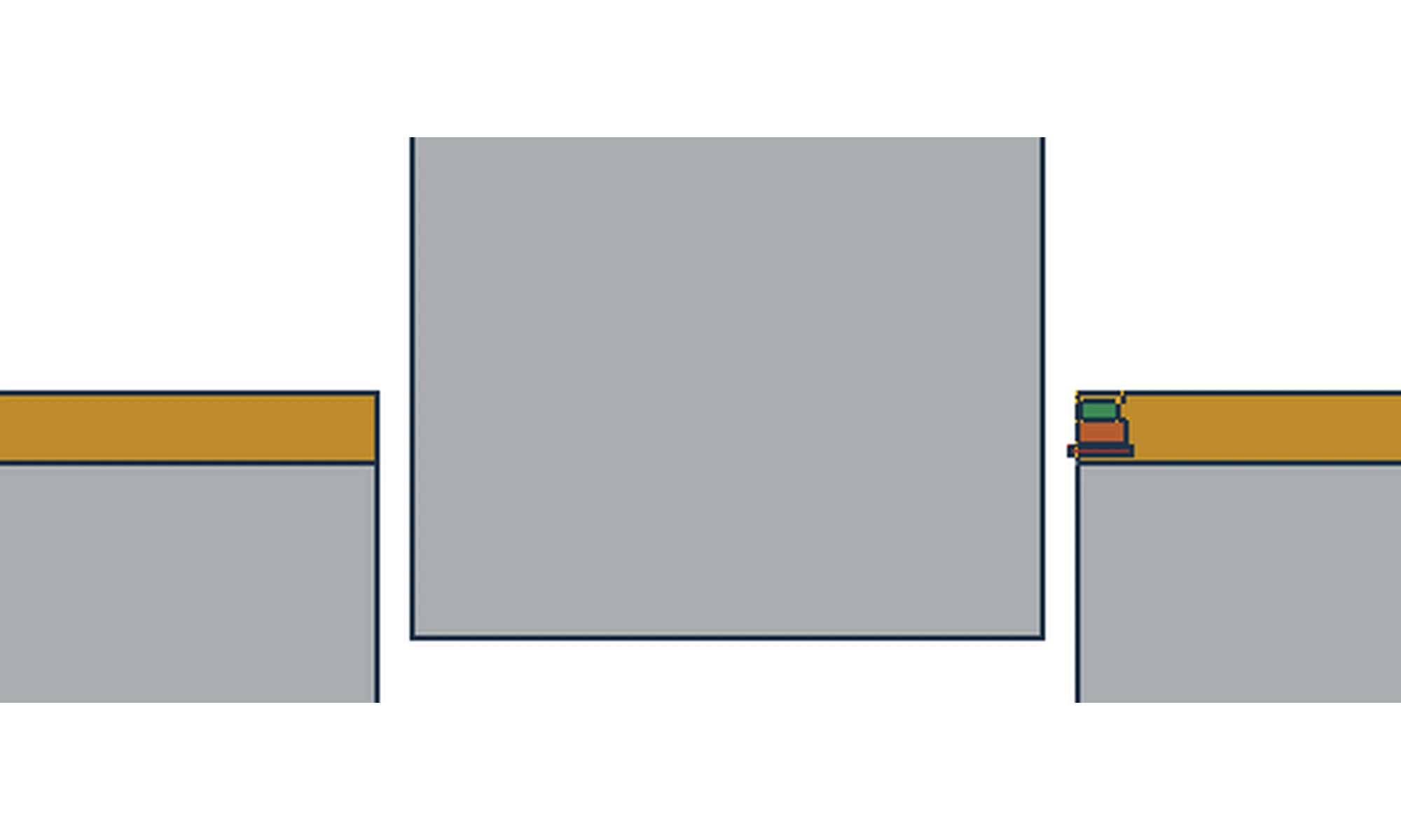
The four zones are a way to locate where the cracks meet, not a terminology quiz. Section the same contour while keeping the entry side, exit side, and feed direction visible. Identify the rollover, the burnished or shiny shear band, the rough fracture zone, and the burr by position. Check whether the zones are uniform around the contour, then compare their proportions and tilt, and only then read burr height.
| Section and burr combination | First candidate | What to check next |
|---|---|---|
| The burnished band narrows, the fracture face tilts more and burrs grow around the contour | Clearance may be too large | Recheck the section, dimensions, and burrs with the same material and tool condition before changing the window |
| Cracks fail to meet, with secondary shearing, two burnished bands or whisker-like burrs | Clearance may be too small | Check sheet thickness, material condition and actual clearance on both sides, including local variation |
| One side of the section and its burrs are pronounced while the other side is relatively normal | Uneven clearance or an alignment issue | Keep the direction mark and run the alignment, guidance, and support checks |
| Only one burr photograph looks abnormal and the other records do not move with it | Insufficient evidence | Do not adjust first; add circumferential position, dimensions and edge-condition records |
The “candidate” column is only a troubleshooting order; one observed feature is not enough for a verdict. Oversized, undersized, and uneven clearance can overlap visually, and material ductility and edge sharpness also change the zone proportions. When the combination is unclear, add evidence instead of inferring actual clearance from one burr photograph.
Do Not Adjust Clearance for a Burr Alone
A larger burr raises a question but does not answer it. Classify the burr as distributed around the contour, fixed to one side, or limited to a few corners. Then place the section and dimensional records beside the burr record.
| Observed distribution | Check first | Decision boundary |
|---|---|---|
| Burrs grow around the contour, while the burnished band narrows and the fracture face tilts more | Overall clearance window | Only when these features occur together should oversized clearance move to the front of the list |
| A fixed side or corner repeats | Alignment, guidance and support | Mark direction and remeasure; do not change clearance directly |
| The abnormality follows one punch or one cutting edge | Edge wear, chipping, or height difference | Number the tool, inspect it closely and compare it with the other edges |
| Dimensions stay stable while a local burr increases | Tool condition and local fit | If the section combination does not support an overall change, pause clearance adjustment and continue the tool check |
A worn edge changes the rollover, burnished band, and burr appearance, and these effects can overlap with an oversized-clearance pattern. If the combinations do not fit, add scrap ejection and material condition to the checklist. Do not write scrap rebound, an oil film, or a local hard spot as a proven single cause.
Separate Local Faults with a Small Trial
Turn «fixed direction» and “follows the punch” into a small controlled trial before choosing the next action:
- Keep the feed direction, operator side and opposite side marked on the sample. Number each punch or cutting-edge position.
- With the same material, thickness and starting window, take consecutive samples. Record burrs, rollover, burnished bandwidth, fracture-face tilt, and dimensions for each direction.
- Compare the sample direction with the die position. If the abnormality stays on the same workpiece direction, check alignment, guidance, and support first. If it follows the same punch or edge, check wear, chipping, and height difference first.
- Remeasure before changing clearance. If the relationship changes after the sample direction or tool position changes, the evidence still cannot separate overall clearance from a local fault.
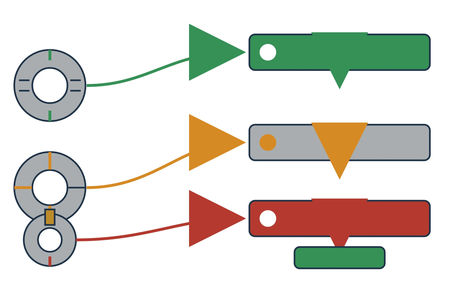
Dimensional records are the second check. When dimensions and burrs shift together, put the overall clearance or alignment near the front of the investigation. When dimensions stay stable but a local burr increases, raise tool condition in priority. These are validation sequences, not substitutes for measuring clearance, guidance, and edge condition.
Freeze the New Parameters After the Trial
Freeze a parameter only when the evidence can be reproduced. Keep material and sheet thickness fixed for each trial and change one primary variable at a time. Retain three records for every round: section photos or microscope observations, dimensional and burr measurements, and tool condition with accumulated strokes.
| Record field | What to specify |
|---|---|
| Material | Grade, supply condition, measured thickness and any required strength or hardness data |
| Convention | One-side c or total C, plus the punch and die references |
| Trial variable | What changed in this round, and whether lubrication, feed height, and edge condition stayed constant |
| Observación | Zone boundaries, all-around or local burrs, dimensions and accumulated strokes |
| Next action | Adjust clearance, correct alignment or guidance, address the edge, or add material evidence |
Put the quality gates on the parameter card before freezing: finished-part dimensions meet the drawing tolerance, burrs meet the drawing or process-sheet limit, the section or burnished band meets the project target, consecutive samples remain stable, and tool condition is recorded. If the project has no burr limit or section target, design and quality must set the gate first; “looks close enough” is not a freeze criterion.
If a gate is not met, return to the preceding branch. If variables changed together, direction was not marked, or tool condition was unknown, repeat the trial with comparable records. Freeze the new material, thickness, clearance convention, trial conditions, and next review condition only when the record can be compared and checked later.
Key Takeaways
Re-establishing blanking clearance after a material or thickness change follows four actions: align the one-side or total convention with the drawing and formula; set a starting window from material, measured thickness, and blanking objective; use the four zones, burr distribution, dimensions, and tool position to separate overall from local problems; then freeze the parameter against defined quality gates. When one burr grows, check the evidence combination before changing clearance.
Our public information shows that MoldSteelLS provides stamping die manufacturing and trial validation. If a material or thickness change needs to be coordinated with mold manufacturing, share the drawing, material condition, and trial record with the engineering team for review. Public product information does not replace measured evidence for this clearance adjustment and does not by itself decide whether to rework the punch or the die.