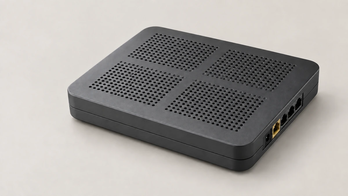
Not necessarily. Adding vent holes changes how much continuous solid material remains in the cover. It also changes how the melt splits around the holes and where the flow fronts meet, but hole count alone cannot predict warpage. A cover bows after ejection or lifts at its corners because structural resistance to deformation, flow orientation and meeting, and differential cooling shrinkage act together.
Do not begin a pre-tooling review by asking, “What is the maximum number of holes we can use?” Start with three sets of information: a 3D product model showing the material and critical assembly features; the gate proposal and mold-flow results; and the cooling-circuit layout with mold-surface temperature results. The gate is the entry through which molten plastic reaches the mold cavity, so it determines where filling begins. Mold-flow analysis simulates how the plastic fills, meets, and cools before tooling begins. If any one of these three inputs is missing, the review shows only part of the cause. During a Molde de inyección de plástico DFM review, moldsteells can examine all three groups of information together. The method below is an actionable review process, not a case study from a specific router project.
Put the three inputs on the Same Table
The first input is the 3D product model. In addition to the vent array, it must show the cover perimeter, the solid webs between holes, ribs, screw bosses, clips, and the mating edge against the bottom housing. Two designs may contain the same number of holes, yet the one that preserves a continuous perimeter and broad divider ribs will generally resist deformation better. Extending holes into corners, beside clips, or across a wide unsupported panel weakens those continuous load paths.
The second input is the gate plan and mold-flow results. The fill-time result answers, “Where does the plastic arrive first, and where does it arrive last?” A weld line is the joint region formed when separated flow fronts meet again; the weld-line result answers, “Where do they meet?” These are not the same plot. To judge whether a weld line is risky, also check its location, the temperature, and pressure at the meeting point, and whether air can escape in time. A completed fill-time color plot does not prove that the weld lines are acceptable.
The third input is cooling information. At minimum, it must include the cooling-circuit layout and mold-surface temperature distributions on both the core and cavity sides. For a typical top cover, the core side usually forms the inner surface, and the cavity side usually forms the cosmetic outer surface, but the actual parting and tool structure govern the final correspondence. When a cooling analysis is available, examine local hot spots and cooling time as well. Lock the material grade before analysis, because changing the same vent array to a different flame-retardant system, filler, or reinforcement can change shrinkage and orientation. Material is an analysis input; it cannot be removed from the question.
Only after all three inputs are available should the following checks begin. When information is missing, obtain it first. Do not approve the design from hole count alone, and do not reject it using an experience-based value that does not state its applicable material and geometry.
Check the Continuous Solid Material Around the Vent Array
Begin by looking at what remains outside the holes. In a router cover, deformation is resisted by the continuous perimeter, the solid webs between holes, reinforcing features across large panels, and unbroken connecting regions around clips and screw bosses. The vent array changes the direction of these solid paths and the panel’s resistance to bending. The degree of weakening must be calculated or simulated using the hole shape, layout, span, material, and the way clips and supports constrain the cover. Open-area ratio, meaning hole area divided by the entire perforated region, cannot by itself predict how much the cover will deform after ejection.
Review four locations:
- Does the outside of the vent array retain a continuous frame, or do the holes extend into the corners and parting edge?
- Do the solid webs remain continuous in one direction, or do staggered holes cut them into narrow zigzag paths?
- Is there enough solid material beside clips, screw bosses, and mating edges to transfer load into the perimeter?
- Does a wide unsupported panel have suitable divider ribs, and could those ribs introduce sink marks or ejection problems?
For initial screening, check the clear web between holes separately from the distance between a hole and an edge. Do not combine them into one universal multiplier, and do not treat any multiplier as a no-warpage acceptance limit. Dimensions must be adjusted for the material, hole shape, perimeter, and actual loading. Local flanges or ribs may reinforce a hole edge, but their dimensions must still be set together with nominal wall thickness, cosmetic sink risk, and ejection conditions. A fixed rib height is not a substitute for that evaluation.
The decision branch is simple. If the continuous perimeter, the connections between holes, and the critical assembly regions are structurally sound, retain the vent array for now and proceed to the flow review. If the solid load paths have been fragmented, create alternatives for the vent pattern, perimeter, or ribs, then rerun the flow and cooling analyses. A dense array is not an automatic reason to remove holes; first identify the specific structure that the holes have disrupted.
Use Weld-Line Results to Evaluate the Gate
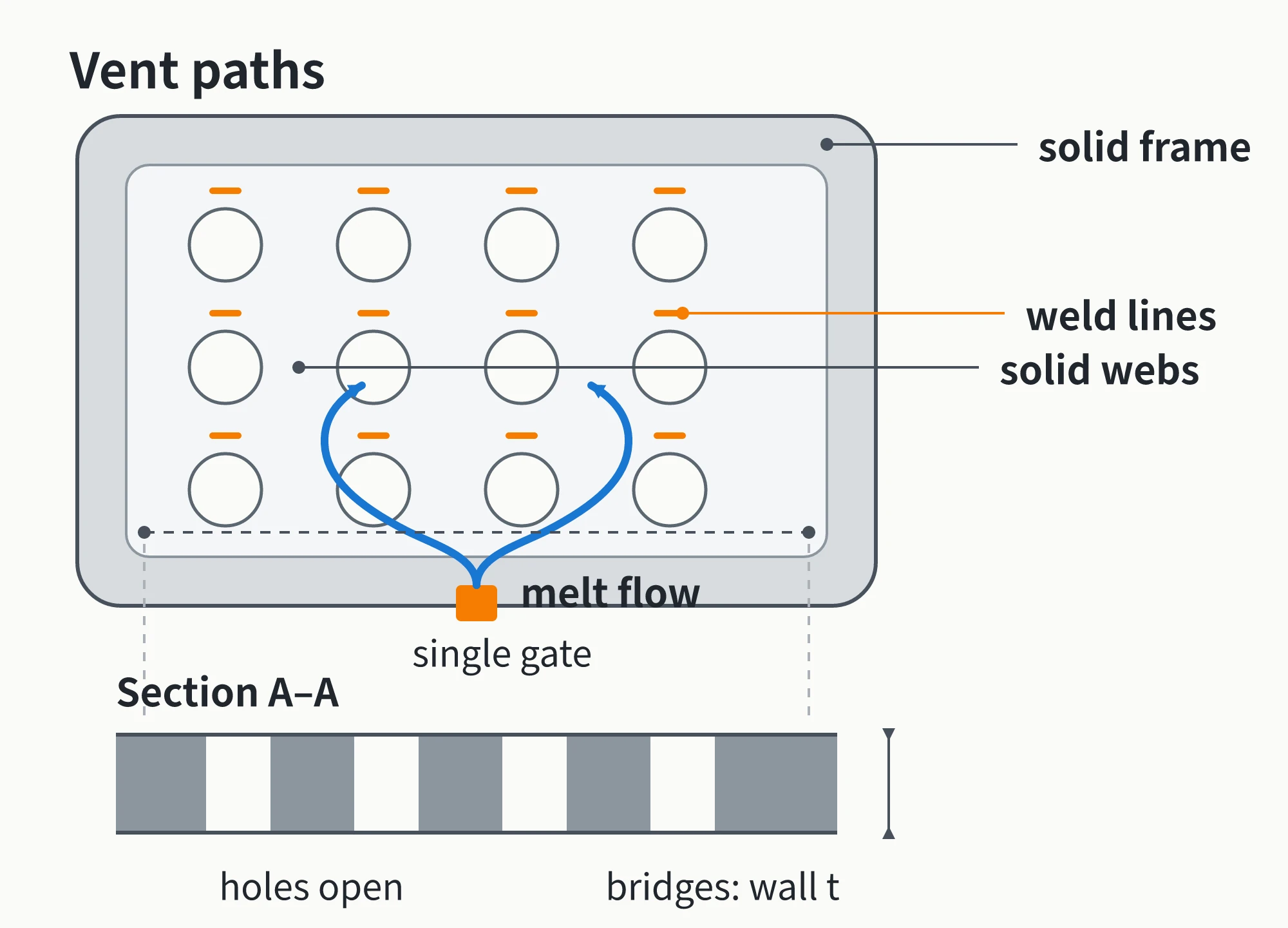
A vent array affects more than stiffness. It repeatedly splits and reunites the advancing flow front. Moving the gate changes the direction in which plastic enters the array, the places where fronts meet, and molecular or fiber orientation. The review cannot rely only on the geometric distance from the gate to the nearest hole. It must evaluate the actual weld-line locations together with the temperature and pressure at meeting and the venting conditions in the tool.
Open the fill-time result first and trace the route from the gate to the vent array. Check whether one front falls clearly behind, whether a local region fills last, or whether another front runs ahead and fills an area earlier than expected. Then open the weld-line result and overlay the meeting locations on the cover’s mating edge, screw bosses, clips, cosmetic surface, and weak connecting regions. Holes increase flow splitting and meeting points, but every hole does not necessarily create a separate, visible, and equally dangerous weak seam.
Use three decision branches:
- If weld lines stay away from critical mating, load-bearing, and cosmetic regions, and the meeting conditions are acceptable, provisionally approve this item.
- If a weld line crosses a clip root, lies near a screw boss, or falls in a critical cosmetic area, compare a relocated gate or a different feeding method first.
- If cosmetic, ejection, or tool-structure constraints limit the gate and the relocated option remains poor, return to the local vent-array and structural alternatives so that the holes and critical regions provide a safer path for the meeting location.
In fabricación de moldes de plástico, changing the gate before steel is cut usually requires only design, simulation, and review iterations. Its cost and risk are far lower than welding, EDM work, and another mold trial after tool steel has been machined, although the change is not cost-free. The required output from this review is not a sentence saying, “Flow is fine.” It is a result image that identifies the gate, critical weld lines, and the disposition for each risk.
Find Directional Cooling Differences and Hot Spots
Passing the structural and weld-line reviews does not guarantee a flat cover. Different mold-surface temperatures on the core and cavity sides cause the inner and outer surfaces to shrink at different rates. A persistently hot region on a broad panel also creates local differential shrinkage. The part may bend toward the hotter, slower-cooling side, but geometry, orientation, and constraints also affect the actual direction. A single rule-of-thumb temperature difference cannot determine it.
Separate two questions. The first is the directional difference between the two sides. Compare the core side, which usually forms the inside of the cover, with the cavity side, which usually forms the cosmetic surface, and check for a persistent mold-surface temperature offset. If the project uses a different parting arrangement, remap the surfaces according to the actual tool structure. Set the project temperature-difference target from the material, geometry, cooling analysis, and drawing requirements rather than using one universal acceptance value. The second question is local hot spots on the same mold surface. Around the broad vented panel, screw bosses, ribs, and thick regions, determine whether circuit coverage remains continuous or the temperature distribution contains isolated peaks.
Do not set waterline distances by applying a fixed multiple of part wall thickness. Distance from a channel to the cavity, channel pitch, and circuit length must be evaluated with channel diameter, flow rate, tool-steel thermal conductivity, and cooling-analysis results. Where conventional drilled circuits cannot reach a hot spot, high-conductivity inserts or conformal cooling can be evaluated. These are candidate solutions, not mandatory features for every vent array.
The decision branches are also clear. If temperatures on the two sides are close and no abnormal local hot spot appears, provisionally approve cooling and retain measurements for the mold trial. If the directional difference is substantial, first verify the circuits, water temperatures, and measurement definitions. If only a local hot spot appears, adjust the circuit, insert, or local structure in that region. Without temperature distributions and a circuit drawing, “the water lines look approximately uniform” is not a conclusion.
When All Three Checks Raise Warnings, Modify the Cause
A practical DFM review rarely finds only one warning. The vent array may leave insufficient continuous solid material, place a weld line across a mating feature, and sit beside a hot spot at the same time. Do not follow a fixed rule that says the holes must change first because they are cheaper. Do not change all three layers at once and lose the ability to identify which change worked.
Write down the fixed constraints first. Thermal and electromagnetic-compatibility requirements determine which vents must remain. Cosmetic requirements determine where a gate is prohibited. Tool structure determines how much room remains for gates and cooling circuits. Then prepare a small number of comparable alternatives. State which layer changes in each alternative, and rerun the flow, weld-line, cooling, and warpage results together.
| Check result | Priority action | What must be rechecked after the change |
|---|---|---|
| The vent array fragments the continuous perimeter or a critical assembly region; flow and cooling show no clear warning | Revise the vent pattern, perimeter, or reinforcing structure | Structural continuity, cosmetic sink risk, and thermal constraints |
| A weld line crosses a critical mating, load-bearing, or cosmetic region; vent-array stiffness is acceptable | Compare gate positions and feeding methods; if constrained, revise the local vent array | Fill time, weld lines, air traps, and locations of critical features |
| The two sides show a clear temperature difference or a local hot spot; structure and weld lines are acceptable | Revise the cooling circuit and evaluate inserts or conformal cooling where needed | Mold-surface temperature, cooling time, and warpage direction |
| Flow and cooling both raise warnings | Create and recalculate separate single-variable alternatives for the vent array, gate, and cooling; combine changes only if one change is insufficient, and record every layer changed | Compare all results under the same boundary conditions |
| None of the three checks shows a clear risk | Freeze this iteration of the vent-array, gate, and cooling design; other DFM and functional requirements still require separate approval | Flatness, mating gap, and critical drawing dimensions |
“First” describes the verification sequence, not a predetermined root cause. Modify only the layer supported by evidence, then recalculate. Otherwise, a change that fixes a weld line may create a new hot spot, or a new rib may introduce sink marks.
Pre-Tooling Release Checklist
Condense the final results into one release checklist so that the review does not end with the vague instruction, “Optimization recommended.”
- Product data: The material grade, nominal wall thickness, vent-array revision, continuous perimeter, ribs, clips, screw bosses, and other critical regions are clearly identified.
- Structural conclusion: The checklist states whether the vent array must change, which solid load path changes, and whether the change affects thermal performance or assembly.
- Flow conclusion: Separate records show the gate plan, fill-time result, and weld-line result. Every critical weld line has an identified location and disposition.
- Cooling conclusion: The cooling-circuit layout, core-side and cavity-side mold-surface temperatures, and local hot spots have corresponding results under consistent operating conditions and measurement definitions.
- Mold-trial verification: Flatness, mating gap, and critical dimensions are measured by methods agreed in the product drawing; “looks flat” is not measurement data.
The product analysis, mold-flow analysis, mold trials, and dimensional inspection capabilities at moldsteells can support the corresponding work on this release checklist. During DFM, we identify structural issues and propose revisions. During mold-flow work, we check filling, mold temperature, shrinkage, and related results. At delivery, we can provide a full-dimensional report. These capabilities do not mean that we have completed the hypothetical router project described here, and they do not replace the acceptance criteria on the customer’s drawing.
Returning to the title question: more vent holes do not automatically make the top cover warp. Check the continuous solid paths left by the array first, then find where the flow fronts meet, and finally determine whether the two surfaces and local regions cool consistently. A pre-tooling DFM review becomes actionable only when all three checks have data, a conclusion, and a decision branch.