Before a block of mold steel reaches the customer’s hands, what exactly happens in between?
The purchasing habit of many mold factories is simple: send over one drawing and wait for one steel block. What processes happen in between, who performs each step, and who is responsible if something goes wrong—these are often not a concern or cannot realistically be tracked.
MoldSteelLS has been engaged in mold steel processing for 18 years. Over these 18 years, the same situation has appeared again and again: after customers receive the finished product, problems show up—incorrect hardness, dimensional out-of-tolerance, heat-treatment deformation—and then no one can clearly identify which process caused the error. The reason is straightforward: steel traders only sell material, machining shops only mill, heat treatment shops only quench, and no one is responsible for the final finished product.
That is why MoldSteelLS has taken over the entire process from start to finish.
Below is the complete path of a block of mold steel from order placement to shipment—8 processes, and each process has its own rules.
Step 1: Clarify Three Things Before Recommending a Steel Grade—Not Simply Giving You Whatever You Ask For
A typical customer request looks like this: “I need one block of H13 for an aluminum alloy die-casting mold.”
At this point, the order is not opened immediately. Three things must be asked first:
- What material will be formed? — Aluminum alloy is about 650°C, copper alloy is about 900°C; this 250°C difference determines whether H13 is sufficient or whether 3Cr2W8V is required.
- What is the annual production volume? — For fewer than 50,000 shots, pre-hardened steel can usually be machined directly; above 200,000 shots, total life-cycle cost must be evaluated systematically.
- Does the cavity have sharp corners or deep ribs? — If yes, hardness must be lowered appropriately, because impact toughness is more important than hardness.
On the Plastic Mold Steel side, P20 and 718H are two entirely different routes. P20 is pre-hardened to HRC 28–35 and is sufficient for common plastics such as ABS, PP, and PE. 718H is raised to HRC 33–38 and is used for medium- to high-volume engineering plastics. If the material is PVC or flame-retardant resin, the correct choice is S136 directly—ordinary steel can rust within days in this kind of corrosive gas environment, and the cavity may be scrapped directly.
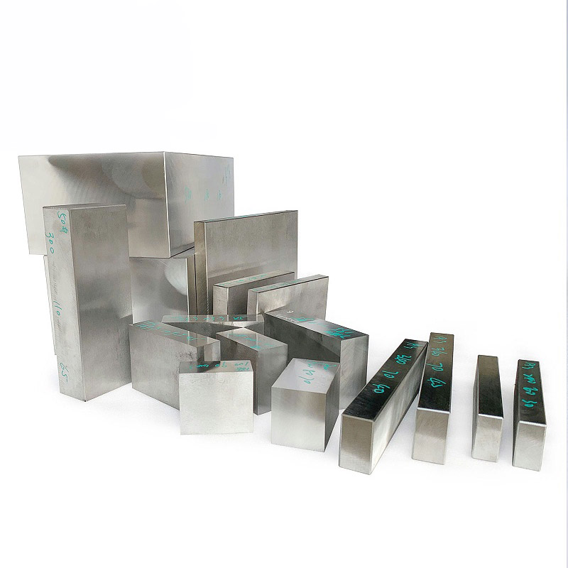
MoldSteelLS’s steel grade portfolio covers three major categories and 18 grades: plastic mold steel from P20 to NAK80, hardware stamping mold steel from CR12 to DC53, and die-casting mold steel including both H13 electric-furnace grade and H13 ESR grade. The logic of material selection is not “the more expensive, the better,” but “working conditions determine the steel grade.”
Step 2: Incoming Material Quality Inspection—Even Material from the Steel Mill Must Pass Three Checks
After the material enters the plant, it does not go directly onto a machine. It first passes through three types of inspection equipment.
Chemical composition analysis. A direct-reading spectrometer (OES) is used for spot testing of chemical composition—actual contents of C, Cr, Mo, and V must not deviate beyond the allowable range of the grade standard. If C is high by 0.05%, brittleness after quenching increases noticeably; if Cr is low by 0.5%, wear resistance drops by a full level. The standard Cr content for H13 is 5.0–5.5%; if the measured result is 4.8%, that block cannot be counted as qualified H13.
Hardness testing. The delivery hardness must fall within the standard range for that grade. P20 in the pre-hardened condition should be HRC 28–35; H13 in the annealed condition should be HRC 18–25. If the value falls outside the range, then either the steel mill’s heat treatment has a problem or the wrong grade has been supplied.
Ultrasonic testing. The probe scans the entire steel block to check for internal porosity, shrinkage cavities, and inclusions. Internal defects in mold steel cannot be seen during machining—the six milled faces may look smooth, but when quenching heats the steel above 1000°C, internal defects can open up directly. Ultrasonic testing identifies hidden risks before the problem actually occurs.
According to the commonly used incoming inspection standard in the domestic mold steel industry (GB/T 4162-2022, with AA grade ≤ 2.0 mm flat-bottom hole equivalent and A grade ≤ 3.2 mm), AA grade acceptance is recommended for precision molds. MoldSteelLS tightens the interception threshold further to 1.0 mm—corresponding to a level above the AA grade standard in GB/T 4162.
Step 3: Rough Machining—Saw Cutting, Six-Side Milling, and Deep Hole Drilling
After quality inspection is passed, the material goes directly into the rough machining workshop.
Band saw cutting. What the customer sends is a finished part drawing—showing final dimensions, tolerances, and surface treatment requirements. MoldSteelLS’s job is to reverse-calculate the required raw block size from the drawing, then confirm it with the customer.
Mold steel is priced by weight. If the raw block is overcalculated by 1 mm, the customer pays real extra money. If it is undercalculated—especially for grades like H13, whose heat-treatment deformation is greater than that of P20—the six faces may not clean up after milling, and the steel block can be scrapped directly. In that case, the lost lead time costs much more than the material itself.
MoldSteelLS’s method is: drawing received → reverse-calculating blank size according to steel grade and the processing level required by the customer → quote and confirming with the customer → cut the material. According to the machining allowance classification in DIN 17350, E0 means no allowance (precision plate, ready for direct mounting by the customer), E1 leaves 0.5–1.0 mm (ground plate), E2 leaves 1.5–3.0 mm (semi-finished plate), and E3 leaves 3.0–6.0 mm (rough-machined block). On this basis, the domestic mold steel industry fine-tunes allowance by grade—H13 has more heat-treatment deformation than P20, so the allowance should be increased by 20–30%. If the customer wants a rough-machined block for further CNC Machining, each side is typically 0.3–0.5 mm oversize relative to the final dimension. If the customer wants a ground plate with reference surfaces already finished, the oversize is 0.1–0.3 mm. If the customer wants a precision plate, it is made exactly to the drawing dimension—there is no concept of “leaving allowance” for a precision plate because it is already the final part.
This is not making money on allowance; it is being transparent with the customer about allowance.
Gantry milling on six faces. The cut steel block is clamped onto a gantry milling machine, and all six faces are milled one by one. The purpose of this step is to create reference surfaces and machining allowance—after six-side milling, the customer can take the block back and put it directly on their CNC machine, without having to re-mill the faces. Not every supplier performs six-side milling—some only provide a bright-rolled steel plate, and the uneven surfaces still have to be corrected by the customer. MoldSteelLS mills until clean metal is fully exposed and controls the flatness of critical surfaces within 0.05 mm, while other surfaces are held to 0.1 mm-class tolerances.
Deep hole drilling. Cooling channels, ejector pin holes, and threaded holes—these all need to be completed before heat treatment. Heat treatment temperatures exceed 1000°C, so drilling holes after quenching is impractical. The length-to-diameter ratio in Deep Hole Drilling can reach 30:1 or even 50:1. During drilling, high-pressure coolant is sprayed through the inside of the drill head to flush chips out—if the drill deviates by even 1 mm, the resulting cooling water path will become uneven.
Step 4: Finish Machining—CNC Milling, Drilling, and Tapping
After rough machining is completed, the material enters the CNC finish machining workshop.
CNC machining allowance control. CNC machining of a steel block and CNC machining of the mold cavity itself are two different things—the latter may involve a precision level of ±0.005 mm, while the former is to provide the customer with reference surfaces and machining stock so the customer can take the block back and mount it directly onto their own CNC equipment for final machining. What level is required depends on the customer’s own equipment and process: do they want a rough-machined block for further CNC finishing, a ground plate with finished reference surfaces ready for clamping, or a precision plate that goes directly onto the machine without further processing? According to the delivery standard for alloy tool steel in JIS G 4404, the thickness tolerance for a ground plate is ±0.05 mm, while a precision plate is tightened further; parallelism and perpendicularity are controlled in accordance with the NADCA #207 acceptance standard for die-casting mold steel. Rough-machined block tolerance is ±0.1 mm, ground plate is ±0.05 mm, and precision plate is ±0.02 mm—with parallelism and perpendicularity all fully ground into place.
To put it plainly, what MoldSteelLS does is not to deliver mold precision at ±0.005 mm—that is the mold factory’s own work. What MoldSteelLS does is ensure that once you receive the steel block, you do not have to spend extra time finding reference surfaces, grinding faces, or opening rough stock—you confirm how much allowance you want first, the faces are milled and ground flat for you, and you can put it straight onto your CNC for finish machining.
Pre-hardened steels (P20, 718H, NAK80, typically delivered at HRC 28–43) can be machined directly on CNC, eliminating the heat treatment step. This is the biggest advantage of pre-hardened steel—no need to do heat treatment yourself, which also eliminates the risk of heat-treatment deformation and cracking.
For quenched-and-tempered steel (such as H13 at HRC 48–52 after quenching and tempering), hard machining requires reduced speed and feed. With coated carbide tools, cutting speed is 20–30% lower than when machining pre-hardened steel, and depth of cut is controlled at 0.2–0.5 mm. Hard machining has two main risks: tool wear causing dimensional drift and excessive cutting temperature damaging the surface. MoldSteelLS uses high-rigidity toolholders with internal cooling, allowing cutting fluid to hit the cutting edge directly from inside the holder—people with 18 years of experience understand that insufficient cooling is equivalent to wasted effort.
Drilling and tapping are also demanding jobs. Tapping an M6 thread in quenched steel carries a much higher risk of tap breakage inside the hole than in soft steel. Excessive torque breaks the tap; insufficient torque produces incomplete threads. Before tapping, MoldSteelLS technicians first check hardness; the tap coating used above 45 HRC is not the same as that used below 40 HRC.
Step 5: Heat Treatment—One Set of Parameters Cannot Manage All Steels
Heat Treatment is not simply throwing steel into a furnace, heating it, and then dipping it in oil—each steel grade has its own austenitizing temperature, soaking time, cooling rate, and tempering temperature window. Get even one parameter wrong, and performance can be cut in half.
MoldSteelLS’s heat treatment equipment covers four stages: quenching, tempering, cryogenic treatment, and nitriding.
Quenching. For H13, the austenitizing temperature is 1020–1040°C—1020°C favors toughness (suitable for complex-cavity die-casting molds), while 1050°C favors wear resistance (suitable for hot extrusion dies). The recommended ranges in ISO 4957:2018 and ASTM A681 are consistent: 1010–1030°C. After soaking, oil quenching or high-pressure gas quenching (6–10 bar nitrogen) is used, with a target cooling rate above 30°C/s to transform austenite into martensite. DC53 has an austenitizing temperature around 1020°C, but its tempering window is 520–530°C—in this range, DC53 undergoes secondary hardening, and hardness does not drop but instead rises to HRC 62–64.
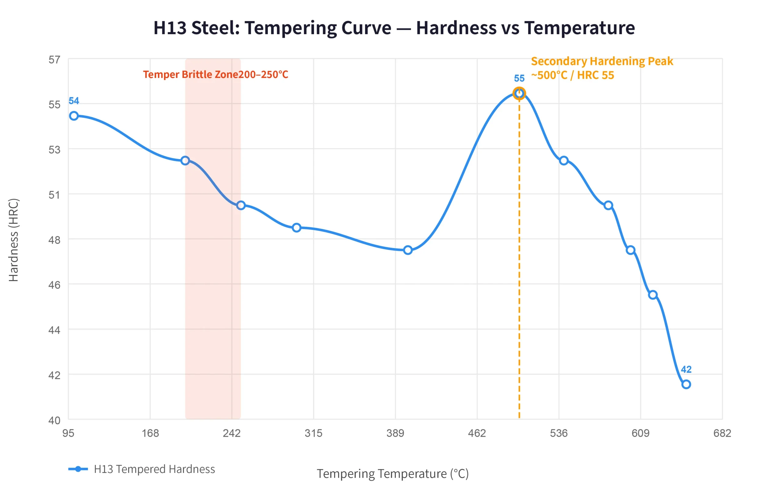
Tempering. Tempering is not done only once. H13 is recommended to be tempered three times, not two—one additional temper converts retained austenite more thoroughly and can extend service life by about 30%. The tempering temperature is 540–620°C, with a target hardness of HRC 48–52. Note: H13 has a secondary hardening peak near 500°C, where hardness can reach HRC 55, but toughness is at its worst—this point must be avoided for die-casting molds.
Carbon tool steel has temper brittleness in the 200–250°C range—within this temperature zone, toughness drops sharply. After quenching, if tempering is performed, it should either be below 200°C or above 250°C; this middle zone cannot be used.
Nitriding. After tempering, nitriding can be added as an optional treatment. At 500–550°C, ammonia or an ammonia-based mixed gas is introduced and held for 8–16 hours, forming a hard but thin compound layer on the surface. After nitriding, H13 surface hardness reaches 60–65 HRC, while the core retains the toughness of 48–52 HRC—surface wear resistance and core impact resistance are both preserved.
Cryogenic treatment. After quenching, the steel part is immersed in liquid nitrogen (-196°C) and held for 2–4 hours. The purpose is to continue transforming retained austenite into martensite. High-carbon, high-chromium steels such as D2 and DC53 gain better dimensional stability after cryogenic treatment, along with additional improvements in hardness and wear resistance.
Step 6: Wire Cutting and EDM—Precision Machining of Hardened Steel After Quenching
After heat treatment is completed, the hardness of the steel part has already reached HRC 48–62. At this point, conventional cutting tools can no longer cut effectively—Wire Cutting / EDM takes over.
Slow wire cutting. A brass wire or zinc-coated wire with a diameter of 0.2–0.3 mm is used to cut in deionized water by electrical discharge. Because the principle is electrical erosion rather than mechanical cutting, workpiece hardness does not affect machining speed in any essential way—DC53 at HRC 60 and P20 at HRC 28 show no fundamental difference in cutting efficiency on a slow wire machine.
Multiple skim cuts are the core process of slow wire cutting. The first cut is a rough cut while leaving 0.05 mm stock; the second skim cut removes the recast layer; the third finish skim cut achieves final dimensions and surface quality. Surface roughness after one cut is Ra 0.8–1.6 μm; after three skim cuts, it can be reduced to Ra 0.2–0.4 μm—saving a great deal of subsequent manual polishing time.
The tolerance of slow wire cutting can be controlled to ±0.005 mm. One detail is easy to overlook: during machining, water temperature must be controlled within ±1°C. If water temperature fluctuation exceeds 2°C, thermal expansion and contraction of the wire diameter will directly cause precision drift.
EDM. Wire cutting handles 2D contours, while EDM handles 3D cavities. A graphite or copper electrode is used to “burn” complex cavity shapes into quenched steel. Electrode wear rate is a key indicator in EDM—graphite electrode wear is 0.1–0.3%, while red copper electrode wear is 0.5–1.0%. Electrolytic copper electrodes are used for finish machining, while graphite electrodes are used for rough machining; different electrodes each have advantages under different discharge parameters.
The common issue in both wire cutting and EDM is the recast layer. The instantaneous discharge temperature reaches 8000–12000°C, causing a microscopically thin layer of metal on the workpiece surface to melt and then cool rapidly, forming a white layer (recast layer) 8–30 μm thick. This layer is brittle and contains microcracks; for high-stress molds, it must be removed by subsequent grinding or polishing.
Step 7: Final Inspection—Only When Three Types of Checks Are Combined Is the Part Qualified
After all machining and heat treatment are completed, the part enters final inspection.
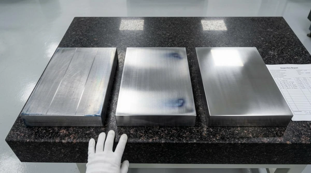
100% dimensional inspection. Critical dimensions are measured item by item against the drawing. Ground plate tolerance is ±0.05 mm (JIS G 4404 standard), and precision plate tolerance is ±0.02 mm (within the ±0.025 mm range of NADCA #207 Premium level). During final inspection, micrometers, bore gauges, and height gauges are used for item-by-item verification. Any part with out-of-tolerance dimensions is reworked directly, without negotiation.
Hardness recheck. No matter how many times hardness has been checked before, it is tested once more before shipment. Hardness after quenching and tempering must fall within the target range—H13 should be HRC 48–52. If it exceeds this range, then either tempering was insufficient (too hard and too brittle) or tempering was excessive (too soft to withstand high temperature).
Inspection report. Every batch is shipped with a complete inspection report: chemical composition analysis data, ultrasonic testing records, heat treatment process parameters (austenitizing temperature, soaking time, tempering temperature, and number of tempering cycles), and final dimensional and hardness data. The value of this document is not only as quality proof—when the customer reorders next time, the heat treatment parameters can be reused directly, without repeated trial and error.
Step 8: Packaging and Delivery—Steel Must Not Be Damaged Before It Arrives
The final step may seem to contain the least technical content, but if it is done poorly, the previous seven processes are wasted.
After quenching, the precision of mold steel is at the ±0.01 mm level. If one corner is bumped during transportation, it can go out of tolerance immediately. MoldSteelLS uses dedicated anti-rust packaging for steel parts: first anti-rust film (VCI vapor corrosion inhibitor), then bubble film, then wooden crate fixation with bolts. The wooden crate is not nailed together casually—the spacing between steel parts inside the crate must not be less than 20 mm, and fixing bolts must not press directly on machined surfaces.
Small parts go by air freight, and large parts go by sea freight. From order placement to shipment, lead time is 3–10 days.
From leaving the steel mill to being assembled into the customer’s mold, one block of mold steel passes through material selection, inspection, rough machining, finish machining, heat treatment, wire cutting/EDM, final inspection, and packaging and delivery—8 processes.
If each process is separated and sourced individually, the market can always offer a lower-priced supplier: cheaper workshops for saw cutting, lower furnace quotes for quenching, and machining stations that charge CNC by the hour. But after building a one-stop system, MoldSteelLS found that the key issue is not the price of each station—it is who is responsible for the final result.
When steel fails, the material selection side says the heat treatment temperature was wrong; the heat treatment side says the incoming material composition was off; the machining side says quenching deformation was too large… In the end, the problem gets passed around until the customer bears it alone—because every station is responsible only for its step.
MoldSteelLS has spent 18 years walking the entire path of this responsibility by itself. It is not that every single station is cheaper than others; it is that someone has connected every station together and followed the result all the way to the end.