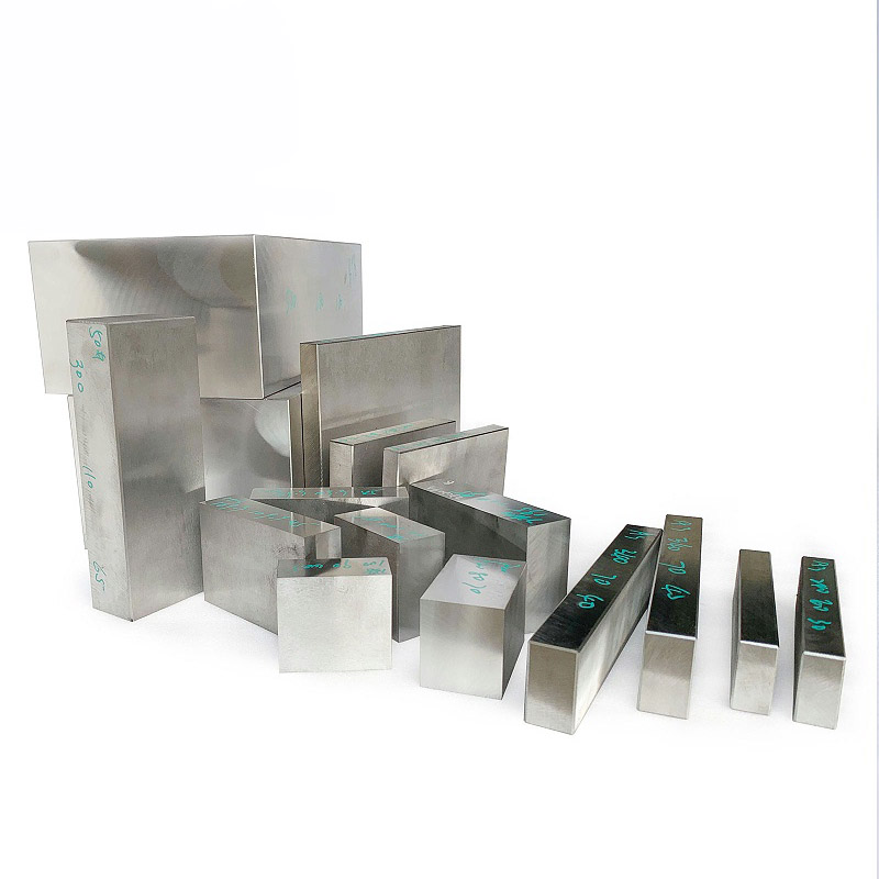
What Is NAK80 Mold Steel?
NAK80 Mold Steel is a pre-hardened mirror-finish plastic mold steel produced by Daido Steel (Japan). It is typically supplied at
about 38–42 HRC, designed for no overall heat treatment, lower risk of machining distortion,
and strong suitability for mirror polishing and precision machining.
Key Features of NAK80
- High hardness & wear resistance: Pre-hardened at 37–43 HRC, offering more stable wear resistance and polish retention for production plastic molds.
- Good machinability: Uniform hardness; complex geometries remain machinable even around 40 HRC.
- Convenient weld repair: Uniform aging response after welding; no full heat treatment required, reducing repair cost.
- Excellent texturing/etching performance: Uniform texture quality, suitable for high-end requirements.
- Outstanding mirror-polishing potential: Can reach a high mirror-finish level (often referenced as #4000–#8000 in polishing-grit terminology) with a clean surface.
- Pre-hardened delivery: Ready for machining without overall heat treatment, reducing deformation risk and shortening lead time.
Note: “#4000–#8000” refers to polishing system grit/industry wording and is not a universal acceptance standard. Actual acceptance should follow
SPI grades, Ra/Rz, or customer-approved samples.
NAK80 Property Tables (Daido Steel Official)
1) Chemical Composition
| Element | Daido Official (Brochure) | Engineering Typical (Common Reference) |
|---|---|---|
| C | 0.15 | 0.15 |
| Si | 0.30 | 0.30 |
| Mn | Proper amount | ~1.50 |
| Ni | 3.00 | 3.00 |
| Mo | 0.30 | 0.30 |
| Cu | 1.00 | 1.00 |
| Al | 1.00 | 1.00 |
2) Physical Properties
| Property | Test Temperature Range | Value & Unit |
|---|---|---|
| Coefficient of Thermal Expansion | 20–100°C | 11.3×10⁻⁶/°C |
| Coefficient of Thermal Expansion | 20–200°C | 12.5×10⁻⁶/°C |
| Coefficient of Thermal Expansion | 20–300°C | 13.4×10⁻⁶/°C |
| Thermal Conductivity | 25°C | 29.5 W/(m·K) |
| Thermal Conductivity | 100°C | 31.4 W/(m·K) |
| Thermal Conductivity | 200°C | 33.0 W/(m·K) |
| Thermal Conductivity | 300°C | 32.8 W/(m·K) |
| Thermal Conductivity | 400°C | 32.1 W/(m·K) |
3) Mechanical Properties
| Property | Value (SI / Metric) | Value (JIS / Imperial) |
|---|---|---|
| Tensile Strength | 1255 MPa | 128 kgf/mm² (183 ksi) |
| Yield Strength (0.2% Offset) | 1010 MPa | 103 kgf/mm² (147 ksi) |
| Elongation | 15.60% | – |
| Reduction of Area | 39.80% | – |
| Charpy Impact Value | 20 J/cm² | 2.0 kgf·m/cm² (2mm U-notch) |
| Hardness | 38–42 HRC | 372–421 HBW |
Typical Applications of NAK80 Mold Steel
- High mirror-finish / high-gloss appearance requirements
- Transparent parts or optical-grade appearance requirements
- High clarity requirements for micro-textures / micro-structures
- EDM-intensive cavities/inserts requiring high surface quality
- Large-area surfaces requiring consistent polishing appearance
Applications Not Recommended for NAK80
- High impact / high shear/edge or cutting areas with high stress
- Ultra-long service life targets (> 1,000,000 cycles)
- High-abrasion materials (glass fiber / mineral-filled resins)
- Strongly corrosive plastics (e.g., PVC)
- Long-term high-temperature operation (> 150°C)
- Cost-sensitive projects without high surface requirements
NAK80 Selection Decision Comparison Table
| Dimension | Recommended Use Cases for NAK80 | Not Recommended Use Cases |
|---|---|---|
| Core Goal & Industry | Extreme appearance & precision: optical lenses, high-gloss 3C housings, cosmetic packaging, light guide plates. | Extreme durability & robustness: continuous stamping, cold-work die edges, ultra-long-life high-volume tooling. |
| Surface Quality Requirement | High-grade mirror finish & fine textures: #4000–#8000 polishing-grit wording (reference), 0.1 mm-class micro-structures, high texture consistency. | General surface requirement: matte, standard fine texture, or highly cost-sensitive plastic parts. |
| Resin & Processing Environment | Common transparent/engineering plastics: ABS, PC, PMMA. Mold temperature typically < 120°C. | High abrasion/high corrosion: glass fiber/mineral-filled resins, corrosive PVC. Mold temperature long-term > 150°C. |
| Mechanical Load & Tool Life | Uniform loading: stable injection pressure, low stress concentration; suitable for medium-to-large production runs. | High-stress loading: high impact, high shear; target life above 1,000,000 cycles. |
| Machining & Compliance Notes | Shorter lead time: avoid overall heat treatment to reduce distortion. EDM-intensive parts require high surface quality. | Special constraints: huge molds (high rigidity sensitivity) or export projects with stringent compliance/testing needs. |
| Economics | 1) Lower total cost: no overall heat treatment, shorter cycle, less polishing labor. 2) Higher value-add: suitable for higher budgets and fast payback projects. | 1) Higher unit cost: over-spec for ordinary parts. 2) Higher maintenance cost for huge molds or ultra-long-life tooling. |
Recommended Cutting Tools for CNC Machining NAK80
| Machining Stage | Recommended Tool Type | Material / Coating / Geometry Suggestions | Typical Model / Brand Reference |
|---|---|---|---|
| Roughing | Indexable inserts / end mills | WC-Co (8–10%) substrate; tough coatings | Mitsubishi VP15TF, ZCC YB205 |
| Semi-finishing | Corn roughing cutter / ball nose | AlCrN coating; 3–4 flutes with variable helix (anti-chatter) | Kennametal, Kyocera series |
| Finishing | Solid carbide ball nose | Ultrafine grain + positive rake; keep cutting edge sharp | Sandvik GC1030, Sumitomo AC530U |
| High-gloss / Mirror | CBN / single-crystal diamond (PCD) | Very high hardness, strong chemical wear resistance; use with high-pressure coolant | Dedicated CBN tools, PCD diamond tools |
Logic for Selecting CNC Cutting Parameters (NAK80)
| Key Factor | Selection Logic | Practical Reference |
|---|---|---|
| Spindle Speed (S) / Cutting Speed (vc) | High speed to reduce the built-up edge. NAK80 is tough; a low cutting speed can lead to a built-up edge. For carbide tools, vc is often suggested at 120–180 m/min. | Roughing: 2500–3500 rpm Finishing: 5000–10000 rpm |
| Feed (F) / Feed per tooth (fz) | Lower feed to reduce chatter and surface waviness. Suggested fz: 0.05–0.15 mm/tooth. | Roughing: 150–200 mm/min Finishing: 60–100 mm/min |
| Depth of Cut (ap) & Stepover (ae) | Shallow cuts to release stress. NAK80 may deform from internal stress; use “thin layers, multiple passes”. | Roughing: 0.5–2.0 mm Finishing: 0.05–0.1 mm |
| Cooling Method | High-pressure cooling to control heat. Prefer oil-based cutting fluid or high-pressure through-coolant. | Pressure reference: 0.3–0.5 MPa |
NAK80 Machining Notes (Pitfall Checklist)
- Pre-hardened delivery: Supplied at ~38–42 HRC; typically machinable without overall heat treatment. Plan finishing allowance by process needs to avoid unnecessary extra work.
- Toolpath sensitivity in deep cavities: Deep-cavity machining can be more sensitive to toolpath direction. Evaluate the rolling direction and deflection risk; adjust the toolpath strategy and tool support as needed.
- Surface quality improvement: With adequate machine rigidity, tooling, and coolant, higher RPM / reasonable cutting speed can reduce built-up edge and drag marks, helping reduce polishing workload.
- Anti built-up edge: Due to Ni/Cu alloying, a lower cutting speed is more likely to cause built-up edge. Keep cutting speed in a reasonable range and tune by tool and cooling method.
- Rust prevention: Rust prevention management is important. Water-based emulsions should be evaluated carefully; clean, dry, and apply rust preventive protection after machining to avoid long exposure.
- Weld repair note: Weld repair has crack risk. Typically, preheating to around 200°C and controlled, slow cooling are recommended to reduce the risk of cracking (depending on the filler, repair area, and heat input).
Typical Problems & Solutions
Q1: What if haze, pinholes, and scratches appear during NAK80 polishing, making it hard to reach “Mirror Level 3”?
Try the following approaches:
- Refine the polishing process into 8 steps, progressing sandpaper grit as:
180# → 320# → 400# → 600# → 800# → 1000# → 1500# → 2000#. - Check hardness and consistency. If hardness is uneven, perform two stabilization treatments before entering the mirror-polishing stage.
- Use imported mirror polishing fluid or diamond polishing paste (W5 → W1.5). Finish with a wool wheel and chromium oxide compound for final luster.
- Control pressure and direction: reduce pneumatic polishing pressure to about 0.25 MPa and maintain a consistent polishing direction to prevent repeated cross-scratches.
Q2: What if local “white haze” appears after polishing (especially at corners), affecting appearance?
Try the following approaches:
- Add cold-air cooling for the polishing area to avoid local overheating (keep temperature below about 60°C).
- Use smaller polishing tools at corners and reduce pressure.
- After polishing, clean with alcohol to remove polishing compound residue.
Q3: What if pinholes cause dimples on molded plastic parts after polishing?
Try the following approaches:
- Select higher-purity NAK80 with S ≤ 0.005%.
- Perform fluorescent penetrant inspection before polishing.
- Use a compatible mold repair compound to fill existing pinholes, then re-polish.
Q4: How to improve efficiency and reduce cost for mirror polishing of NAK80 molds?
Try the following approaches:
- Introduce robotic polishing for rough and mid polishing, keeping only final mirror finishing as manual work.
- Use dedicated NAK80 polishing wheels to improve cutting efficiency.
- Build a polishing parameter database to standardize operations.
Q5: What if cracks appear after weld repair on NAK80?
Try the following approaches:
- Preheat to 200–250°C using ceramic heaters or induction heating for uniform temperature rise.
- Use low-hydrogen / crack-resistant consumables such as WE600 special alloy steel electrodes or ERNiCrMo-3 nickel-based filler wire.
- Use low current with multi-layer multi-pass welding or segmented back-step technique; control interpass temperature at 200–220°C.
- Immediately cover with asbestos cloth for slow cooling, then stress-relief at 280–300°C × 1.5–2 hours.
Q6: What if hardness/strength is not acceptable after weld repair?
Try the following approaches:
- If hardness is insufficient: use “base layer + WC-reinforced top layer” overlay welding, then temper at 250°C for 1 hour.
- If hardness is too high and machining is difficult: use low-carbon filler, temper at 350°C × 2 hours, and machine with carbide tools at high speed and low feed.
- If strength is insufficient: increase groove angle to 60°, use three-layer welding to ensure penetration, choose ER110S-G high-strength wire, preheat to 280°C, then temper at 320°C × 2 hours.
Q7: What if porosity, color difference, or mirror finish is not achieved after weld repair?
Try the following approaches:
- Remove porosity: clean the area with acetone; bake electrodes at 350°C for 1 hour; use 2–3 mm short-arc uphill welding and increase travel speed to reduce molten pool residence time.
- Reduce color difference: use filler with similar composition; control heat input to reduce oxidation; apply local heat treatment and tone-matching polishing.
- Meet mirror finish: use pulsed TIG and dedicated filler wire; leave 0.1 mm stock after precision grinding; polish progressively with diamond paste 800#–8000#, then finish with wool wheel for mirror appearance.
Q8: What if hardness is insufficient after heat treatment?
Try the following approaches:
- Low-temperature aging strengthening: 500–530°C staged holding for 2–3 hours; strictly control heating rate ≤ 100°C/hour; furnace cooling.
- Double aging: 500°C × 2 hours air cool, then 530°C × 3 hours furnace cool; use polymer quench fluid to increase cooling rate when applicable.
- Local/overall re-hardening: for machined parts, local induction heating (850°C × 30 s + spray cooling + 200°C temper). For unmachined parts, re-austenitize at 840–870°C for 1.5–2.5 hours, then isothermal quench and age at 520–540°C.
- Surface nitriding: gas nitriding at 500°C for 3 hours; 180°C low-temperature temper; control case depth at 0.1–0.2 mm.
Q9: What if hardness is uneven after heat treatment?
Try the following approaches:
- Vacuum quenching + aging: 840°C vacuum heating for 1.5 hours; oil cool to 150°C then temper at 200°C; age at 520°C for 3 hours; maintain temperature uniformity ±3°C.
- Stress relief + overall aging: 550°C × 2 hours anneal, then 530°C overall aging for 3 hours.
- Local heating + overall aging: locally induction heat low-hardness areas to 840°C, then age overall at 530°C; repeat local treatment if still not acceptable.
- Adjust process parameters: increase quench temperature (860–870°C), extend holding time, and use two-stage tempering to optimize precipitate distribution.
Q10: What if hardness is abnormal (too high/brittle)?
Try the following approaches:
- High-temperature temper to reduce hardness: 600°C × 2 hours to relieve stress, then age at 520°C for 3 hours; heating rate ≤ 50°C/hour to reduce cracking risk.
- Vacuum slow-cooling aging: hold at 520°C for 3 hours, cool slowly at 20°C/hour to reduce thermal stress.
- Targeted adjustments: confirm alloy composition first, then fine-tune austenitizing temperature, cooling rate (control at 50–60°C/s), and tempering process to balance hardness and toughness.
- Low-temperature pre-treatment: add 150°C × 1 hour pre-treatment before aging to reduce deformation and stabilize hardness.
NAK80 Datasheet Download
| Item | Details |
|---|---|
| File | NAK80 Datasheet |
| Type | |
| Size | 640 KB |
| Link | https://moldsteells.com/wp-content/uploads/2026/01/NAK80-Mold-Steel-Explained-Properties-Machining-Pitfall-Checklist.pdf |